28
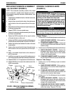
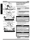
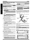
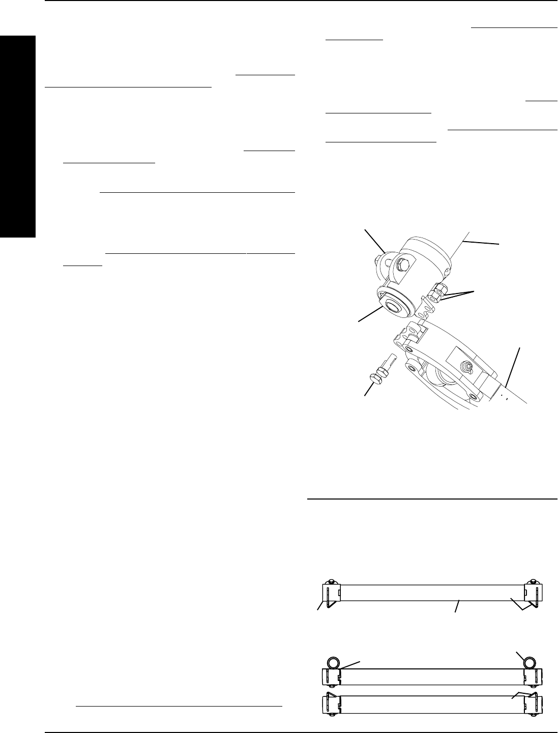
DETAIL "A" - CLAMP POSITION
NOTE: Axle tubes are viewed from the FRONT of the
wheelchair.
NOTE: Socket facing DOWN not shown for clarity.
STANDARD CLAMP POSITION - TABS/SOCKETS DOWN
INVERTED CLAMP POSITION - TABS/SOCKETS UP
Camber Clamp
Axle Tube
Tab DOWN
F
R
A
M
E
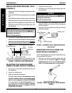
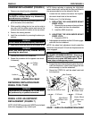
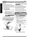
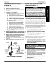
PROCEDURE 4 FRAME
REPOSITIONING THE AXLE TUBE
(FIGURES 14 AND 15)
NOTE: This procedure should only be performed if chang-
ing the front seat-to-floor height. Refer to
ADJUSTING
FRONT SEAT-TO-FLOOR HEIGHT in PROCEDURE
5 of this manual.
NOTE: Right and left are determined by standing be-
hind the wheelchair.
1. Open both the camber clamps. Refer to OPENING/
CLOSING CLAMPS in this procedure of the manual.
2. Remove the rear wheels from the camber inserts.
Refer to
REMOVING/INSTALLING REAR WHEELS
in PROCEDURE 5 of the manual.
3. Remove the camber inserts from the wheelchair (FIG-
URE 14).
4. Refer to
ADJUSTING FRONT SEAT-TO-FLOOR
HEIGHT in PROCEDURE 5 of the manual to deter-
mine the proper position for the axle tube.
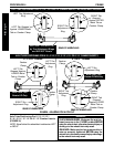
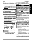
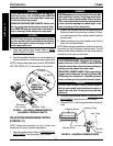
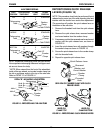
5. Refer to the chart in FIGURE 15 to determine the
proper axle tube adjustment.
NOTE: Refer to DETAIL "B" of FIGURE 15 for telescop-
ing tube and clamp hole patterns.
6. Remove the locknuts and hex bolts securing the tele-
scoping tubes to the camber clamps.
7. Perform one (1) of the following:
A. CLAMP POSITION MUST BE INVERTED- Pro-
ceed to STEP 8.
B. CLAMP POSITION REMAINS IN STANDARD
POSITION - proceed to STEP 12.
8. Remove the RIGHT camber clamp from the axle
tube and set aside.
9. Remove the LEFT camber clamp from the axle tube.
10. Position the LEFT camber clamp onto the RIGHT
end of the axle tube with the metal tabs facing the
inside of the wheelchair.
11. Repeat step 10 for the RIGHT camber clamp and
the LEFT end of the axle tube.
NOTE: The camber clamps should now be inverted, as
shown in DETAIL "A" of FIGURE 14.
12. Align the camber clamp mounting holes with the tele-
scoping tube holes determined in STEP 5.
13. Secure telescoping tube to camber clamp with hex
bolts and locknuts.
14. Insert camber inserts into axle tube with lowest degree
of camber facing towards outside of the wheelchair.
15. Install the rear wheels into the camber inserts. Refer
to
REMOVING/INSTALLING REAR WHEELS in
PROCEDURE 5 of this manual.
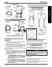
Axle Tube
Camber Clamp
Telescoping
Tube
Hex Bolt
Locknuts
Camber
Insert
Socket UP
Tab UP
16. Adjust the axle tube. Refer to ADJUSTING THE
AXLE TUBE in this procedure of the manual.
NOTE: The performance of the wheelchair will be af-
fected if the axle tube has not been adjusted to correct
the toe in/toe out of the wheelchair.
17. Ensure the camber clamps are closed. Refer to OPEN-
ING/CLOSING CLAMPS in this procedure of the manual.
18. Adjust anti-tippers. Refer to
ANTI-TIPPER ADJUST-
MENT/REPLACEMENT in PROCEDURE 7 of the
manual.
NOTE: QUICK RELEASE LEVERS ONLY - Reposi-
tion the quick release levers to the top/bottom of the
axle tube if desired. Refer to REPOSITIONING QUICK
RELEASE LEVERS in this procedure of the manual.
FIGURE 14 - REPOSITIONING THE AXLE TUBE
NOTE: LEFT camber clamp and telescoping tube not
shown for clarity.
NOTE: Suspension telescoping tube shown. Non-sus-
pension telescoping tube attaches to camber clamp in
the same manner.
Camber Clamp


