


7
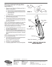
B. Remove the hand brake.
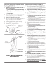
C. Turn the adjustment lever COUNTERCLOCK-
WISE.
D. Insert push handles into side frames with the hand
grip facing the back of the rollator.
3. Perform one (1) of the following:
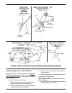
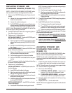
INSTALLING BRAKE KIT (BEFORE 3/7/00) -
Install NEW hand brake.
A. Position the handbrake assembly under the push
handle so the lock button is facing OUT, the tip of
the hand brake is towards the end of the hand grip
and the brake cable is AWAY from the hand grip.
B. Position the hook portion of the hand brake clamp
through the slot in the hand brake assembly.
C. Install the washer, hex bolt and locknut to secure
the hand brake assembly to the push handle.
D. Securely tighten the locknut.
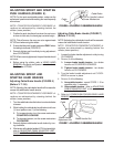
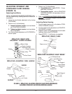
INSTALLING BRAKE KIT (AFTER 3/8/00) - Install
NEW hand brake.
A. Push the NEW hand brake onto the push handle.
NOTE: If necessary, twist the hand brake while pushing to
install on the push handle.
B. Align the mounting holes of the NEW hand brake with
the mounting hole in the push handle.
C. Install the phillips screw through both mounting holes.
Securely tighten.
D. Apply a thin coat of hair spray on the inside of the
foam grip and on the push handle.
NOTE: This application will make it easier to slide
the grip onto the push handle.
E. Slide new grip onto one end of the push handle.
4. Adjust the push handle. Refer to
ADJUSTING SPRINT
AND SPARTAN PUSH HANDLES in this instruction sheet.
5. Adjust the hand brake. Refer to
ADJUSTING SPRINT
AND SPARTAN HAND BRAKES in this instruction sheet.
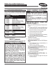
INSTALLING/REMOVING THE HAND
BRAKE (BEFORE 3/7/00) - STEPS 2 AND 3
Hex Bolt
(STEPS
2A AND 3C)
Washer
(STEPS
2A AND 3C)
Locknut
(STEPS
2A AND 3C)
Hand Brake
(STEP
2B AND 3A)
Push Handle
Lock Button
Hook
(STEP 3B)
Hand Brake Clamp
(STEP 3B)
Slot
(STEP 3B)
Phillips Screw
Hand Brake
Push Handle
Hand Brake
Adjustment
Nut
Hand Brake Nut
Hand Grip
Mounting Hole
INSTALLING/REMOVING THE HAND
BRAKE (AFTER 3/8/00) - STEPS 2 AND 3
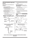
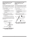
INSTALLING PUSH HANDLE
- STEPS 2 AND 3
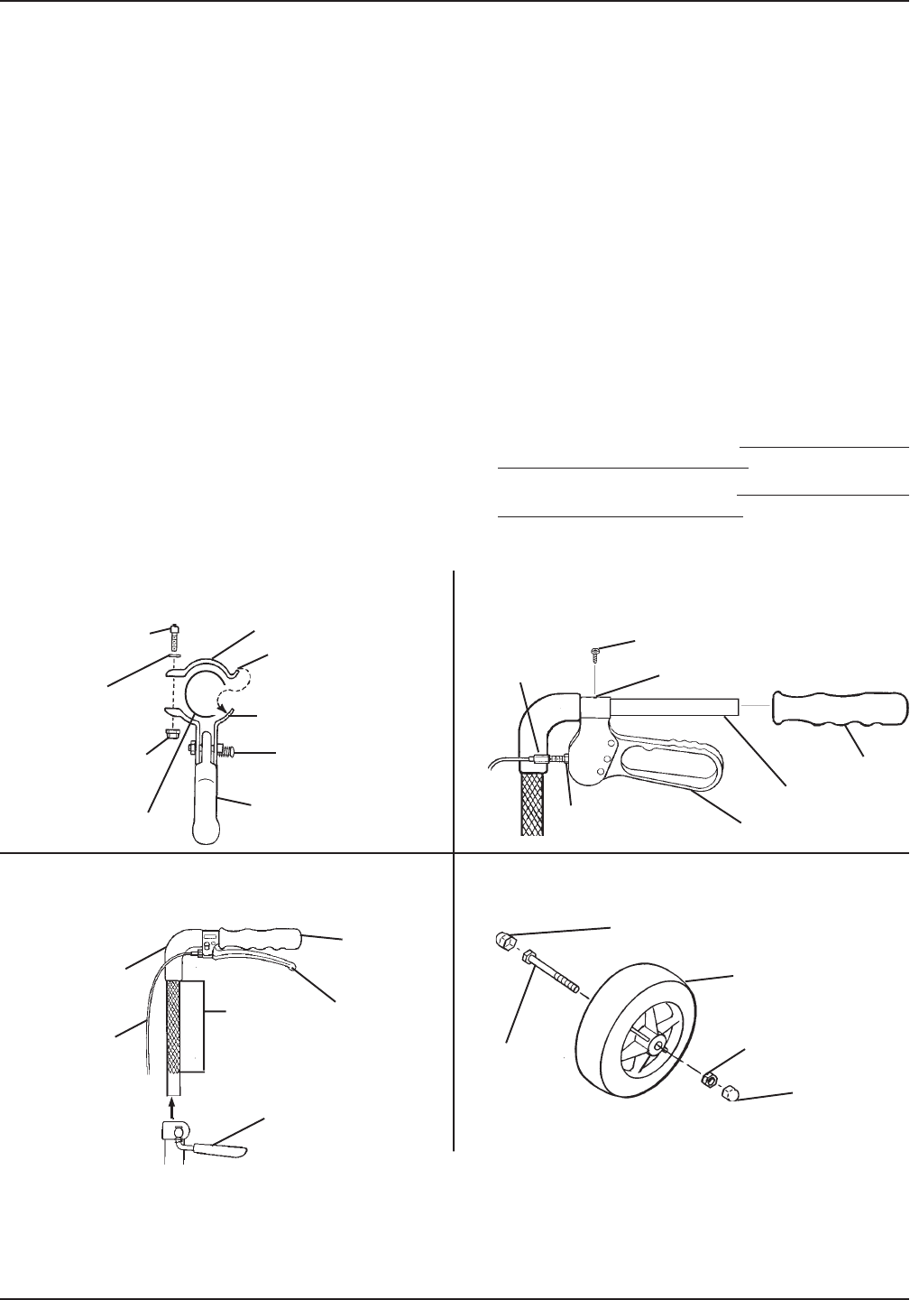
INSTALLING THE TIRE - STEP 1
Cap Cover
(STEP 3A)
Screw
(STEP 3B)
Locknut
(STEP 3B)
Cap Cover
(STEP 3A)
Tire
(STEP 3C)
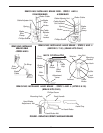
FIGURE 5 - REPLACING SPARTAN CANES AND BRAKES - ASSEMBLING SPARTAN FOR USE
Adjustment Lever
(STEP 2A)
Push Handle
(STEPS 2D
AND 3A)
Tip of Hand
Brake
(STEP 3A)
Hand Grip
(STEP 3A)
Brake Cable
(STEP 3A)
Textured
Tubing