


10
REPLACING STINGRAY AND
STARGAZER BRAKES (FIGURE 10)
NOTE: COUNTERCLOCKWISE/CLOCKWISE direc-
tions are determined by standing beside the rollator.
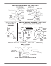
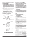
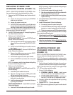
1. Remove the EXISTING brake wire. Perform the fol-
lowing:
A. Loosen the hex screw securing the EXISTING
brake wire to the brake.
B. Loosen the caster housing nut.
C. Pull EXISTING brake cable up to pull brake wire
through the hole in the brake and through the caster
housing nut and caster housing adjustment nut.
NOTE: It may be necessary to straighten the end of the
brake wire to pull it through the brake.
2. Pull EXISTING brake cable UP through the guide on
the rollator frame to remove.
3. Perform one (1) of the following:
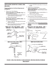
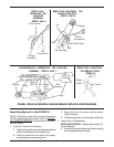
INSTALLING CANE KIT - Remove EXISTING push
handle. Perform the following:
A. Remove adjustment knobs and screws from both
sides of the frame by turning COUNTERCLOCK-
WISE.
B. Pull UP on the EXISTING push handle to remove
from frame.
INSTALLING BRAKE KIT - Remove EXISTING hand
brake. Perform the following:
A. Remove the phillips screw securing the EXIST-
ING hand brake to the push handle.
B. Pull the back support out of the push handle.
C. Pull the EXISTING hand brake off of the push
handle.
NOTE: If necessary, twist the hand brake while pulling
to remove it from the push handle.
4. Perform one (1) of the following:
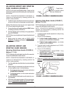
INSTALLING CANE KIT - Install NEW push handle. Per-
form the following:
A. Insert NEW push handles into frames.
B. Align the mounting holes of the NEW push handle
with the mounting holes in the frame.
C. Install the screw from the inside of the frame through
both sets of mounting holes.
D. Install the adjustment knob on the outside of the frame
by turning CLOCKWISE.
INSTALLING BRAKE KIT - Install NEW hand brake.
Perform the following:
A. Push the NEW hand brake onto the push handle.
NOTE: If necessary, twist the hand brake while pushing to
install on the push handle.
B. Push the back support into the push handle.
C. Align the mounting holes of the NEW hand brake with
the mounting hole in the push handle.
D. Install the phillips screw through both mounting holes.
Tighten until snug.
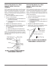
5. Thread NEW brake cable DOWN through the guide on
the rollator frame.
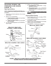
6. Install NEW brake wire. Perform the following:
A. If necessary, loosen the caster housing nut.
B. Thread NEW brake wire through caster housing ad-
justment nut , caster housing nut and hole in brake.
C. Tighten hex screw to secure NEW brake wire to brake.
NOTE: If necessary, bend the excess brake wire UP to keep
it from interfering with brake action.
7. Adjust the push handle. Refer to ADJUSTING STINGRAY
AND STARGAZER PUSH HANDLE in this instruction
sheet.
8. Adjust the hand brakes. Refer to
ADJUSTING STIN-
GRAY AND STARGAZER HAND BRAKES in this in-
struction sheet.
ADJUSTING STINGRAY AND
STARGAZER PUSH HANDLE
(FIGURE 10)
NOTE: COUNTERCLOCKWISE/CLOCKWISE direc-
tions are determined by standing beside the rollator.
NOTE: For the most comfortable position, make sure the
adjustment is performed while wearing the most frequently
worn shoes.
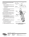
1. Position the push handle so that when the user’s arm
is down to their side, the hand grip is at wrist height.
NOTE: This will ensure the arms are at an approximate
20
o
- 30
o
bend when using the rollator.
2. Do one (1) of the following:
A. STINGRAY (MODEL 65500) - install screw
into one (1) of the six (6) adjustment holes.
B. STARGAZER (MODEL 65600) - install screw
into one (1) of the four (4) adjustment holes.
3. Securely tighten with adjustment knob by turning
CLOCKWISE.
4. Repeat STEPS 1 - 3 for the other side.
NOTE: When securely tightened, the push handles should
not move.