


29
R
E
A
R
W
H
E
E
L
S
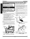
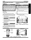
1-1/2 to 2-inch Clearance
Front Release Button
Anti-tipper
Anti-tipper
Mounting
Bracket
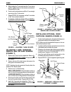
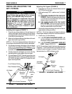
FIGURE 7 - INSTALLING ANTI-TIPPERS
Ground
PROCEDURE 7REAR WHEELS
INSTALLING/ADJUSTING THE
ANTI-TIPPERS
WARNING
Anti-tippers MUST be fully engaged and re-
lease buttons fully protruding out of release
button holes BEFORE using wheelchair.
DO NOT operate the wheelchair if the anti-
tippers CANNOT be positioned so that they
extend BEYOND the outer edge of the rear
wheels or if a 1-1/2 to 2-inch clearance
CANNOT be acheived - otherwise injury
or damage may occur. Contact a quali-
fied technician.
Installing Anti-tippers (FIGURE 7)
1. Press the rear release buttons of the anti-tipper and
insert the anti-tipper into the opening in the anti-tipper
mounting bracket until the front release buttons lock
in into the front mounting hole.
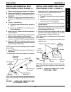
2. Measure the distance between the bottom of the anti-
tipper wheel and the ground/floor.
NOTE: A 1-1/2 to 2-inch clearance between the bottom of
the anti-tipper wheels and the floor must be maintained.
3. If the distance between the bottom of the anti-tipper
wheel and the ground/floor is NOT between 1-1/2 to
2-inches refer to
ADJUSTING ANTI-TIPPERS in this
procedure of the manual.
4. Visually inspect the anti-tippers to ensure that they
extend beyond the outer edge of the rear wheel.
5. If the anti-tippers DO NOT extend beyond the outer
edge of the rear wheel, contact a qualified technician
for a NEW anti-tipper model OR to adjust the anti-
tipper mounting bracket.
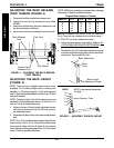
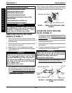
Rear Release Button
Front
Mounting
Hole
Rear Mounting Hole
(DO NOT USE)
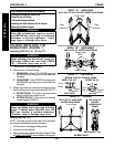
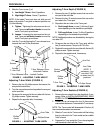
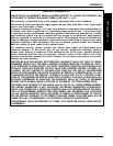
Adjusting Anti-tippers (FIGURE 8)
1. Press down on the two (2) release buttons near the
BOTTOM of the anti-tipper.
2. While performing STEP 1, perform one (1) of the fol-
lowing:
A. FOR WHEELCHAIRS WITH THE LONG ANTI-
TIPPERS - Slide the anti-tipper extension to one
(1) of the five (5) mounting holes and allow the
release button to lock into place.
B. FOR WHEELCHAIRS WITH THE SHORT
ANTI-TIPPERS - Slide the anti-tipper extension
to one (1) of the three (3) mounting holes and
allow the release button to lock into place.
3. Measure the distance between the bottom of the anti-
tipper wheel and the ground/floor.
NOTE: A 1-1/2 to 2-inch clearance between the bottom of
the anti-tipper wheels and the floor must be maintained.
4. Perform one (1) of the following:
A. 1-1/2 TO 2-INCH CLEARANCE EXISTS - Ad-
just the anti-tippers on the opposite side of the
wheelchair to this position.
B. 1-1/2 TO 2-INCH CLEARANCE
DOES NOT
EXIST - Repeat STEPS 2-3.
NOTE: If the anti-tipper height has been adjusted and the
necessary 1-1/2 to 2-inch clearance cannot be achieved,
a different model anti-tipper is required. Contact a quali-
fied technician for a NEW anti-tipper model.
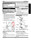
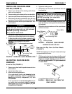
FIGURE 8 - ADJUSTING ANTI-TIPPERS
1-1/2 to 2-inch Clearance
Release
Button
Anti-tipper
Mounting
Holes
Ground
Anti-tipper
Extension