


24
Socket
Screws
Arm Pad
Phillips
Screw
T-Arm Post
Arm Tube
NOTE: If
necessary, turn
arm tube 180
o
to obtain two (2)
positions.
Phillips Screw
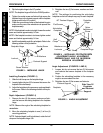
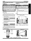
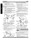
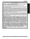
FIGURE 5 - ADJUSTING T-ARM DEPTH
Adjusting T-Arm Depth (FIGURE 5)
1. Remove the two (2) phillips screws that secure the
arm pad to the arm tube.
2. Remove the two (2) socket screws that secure the
arm tube to the T-arm post.
3. Reposition the arm tube on the T-arm post:
A. Desk Length Arms - to one (1) of three (3) posi-
tions depending on the desired arm pad depth.
B. Full Length Arms - to one (1) of five (5) positions
depending on the desired arm pad depth.
NOTE: Additional positions are obtainable by turning the
arm tube 180
o
.
4. Re-secure the arm tube to the T-arm post with the
two (2) socket screws. Torque to 60-70 in./lbs.
5. Reattach the arm pad to the arm tube with the two (2)
phillips screws. Tighten securely.
6. Repeat for the opposite side, if necessary.
A
R
M
S
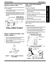
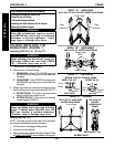
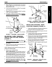
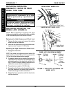
FIGURE 3 - ADJUSTING T-ARM HEIGHT
Set
Screws
T-Arm Release Lever -
Unlocked Position
Outside
T- Arm Post
T-Arm Release Lever - Locked Position
2. Slide the T-arm to one (1) of:
A. Low Height T-Arms - Nine (9) positions.
B. High Height T-Arms - Seven (7) positions.
NOTE: If the inside T-arm post does not slide up and
down in the outside T-arm post as desired, perform one
(1) of the following:
A. Tighten - Tightening the set screws on the out-
side T-arm post will make it harder to move the
inside T-arm post up and down.
B. Loosen - Loosening the set screws on the out-
side T-arm post will make it easier to move the
inside T-arm post up and down.
3. Lock the T-arm by flipping the T-arm release lever
towards the front of the wheelchair.
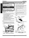
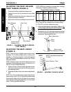
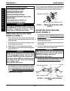
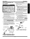
FIGURE 4 - ADJUSTING T-ARM WIDTH
Phillips
Screw
Arm Tube
Phillips Screw
Arm Pad
Adjusting T-Arm Width (FIGURE 4)
1. Remove the two (2) phillips screws that secure the
arm pad to the arm tube.
2. Turn the arm pad around and reposition the arm pad
on the arm tube.
3. Re-secure the arm pad to the arm tube with the two
(2) phillips screws. Tighten securely.
4. Repeat for the opposite side, if necessary.
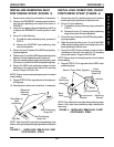
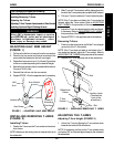
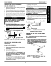
Adjusting T-Arm Sockets (FIGURE 6)
1. Remove the rear wheels from the wheelchair, if nec-
essary. Refer to INSTALLING/REMOVING REAR
WHEELS in PROCEDURE 7 of this manual.
2. Loosen, but do not remove the four (4) hex screws
and washers that secure T-arm socket to T- arm clamp.
NOTE: The T-arm socket will disassemble if the four (4)
hex screws and washers are removed.
3. Slide the T-arm into the T-arm socket until the locking
lever is in the slot in the T-arm socket and an audible
"click" is heard.
4. Squeeze the T-arm socket the T-arm clamp together
until the socket is flush with the T-arm.
PROCEDURE 6 ARMS
Inside T-Arm
Post