


16
PROCEDURE 3 FRONT RIGGINGS
3. Retighten the two (2) flat screws, washers and lock-
nuts.
NOTE: The settings for positioning the articulating
footplates on the half-clamps may vary for each footplate.
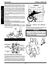
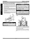
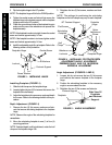
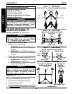
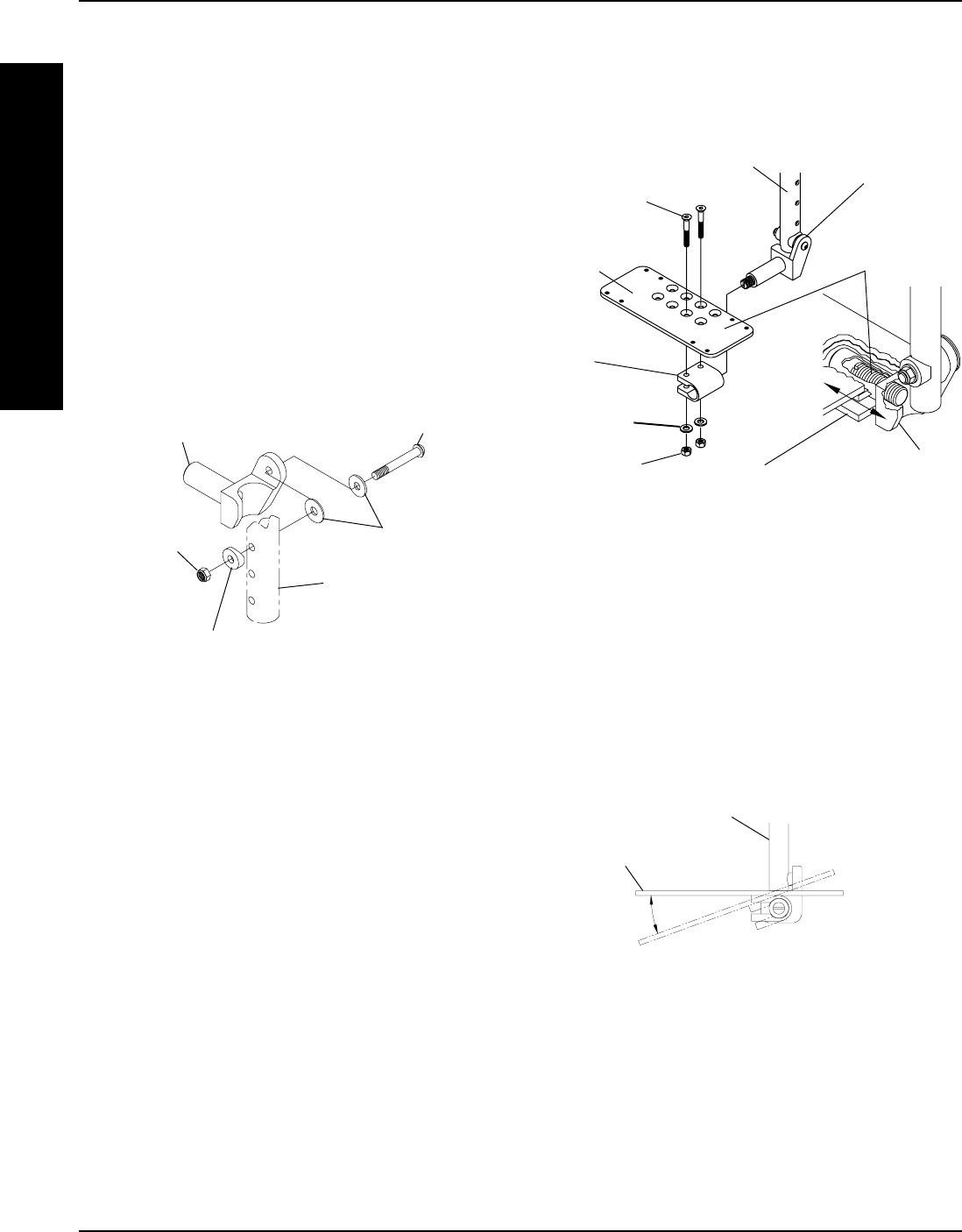
Footrest Support
Washers
Coved Washer
Locknut
FIGURE 3 - INSTALLING HINGE
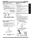
Footplate Hinge
Socket Screw
Nylon
Adjustment
Screw
Footplate
Hinge
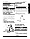
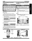
Half
Clamp
Articulating
Footplate
Flat Screws
Half Clamp
Locknuts
Washers
90
o
Footrest Support
Footplate Hinge
FIGURE 4 - INSTALLING FOOTPLATE/DEPTH
ADJUSTMENT/ANGLE ADJUSTMENT/
PERPENDICULAR AND/OR INVERSION/
EVERSION ADJUSTMENT
3. Flip the footplate hinge to the UP position.
NOTE: The footplate hinge will fall to the DOWN position.
4. Tighten the socket screw and locknut that secure the
footplate hinge to the footrest support until the footplate
hinge remains in the UP position.
5. Check the up and down motion of the footplate hinge to
make sure the user of the wheelchair can operate the
footplates easily.
NOTE: If the footplate's motion is too tight, loosen the socket
screw and locknut approximately 1/4-turn.
NOTE: If the footplate's motion is too loose, tighten socket
screw and locknut approximately 1/4-turn.
6. Install the adjustable angle flip-up footplate. Refer to the
following section of this procedure.
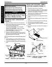
Installing Footplate (FIGURE 4)
1. Slide the half clamp over the footplate hinge.
2. Loosely tighten the two (2) flat screws that secure the
footplate to the half clamp.
3. Adjust the footplates to the necessary angle and depth
for the user. Refer to the following sections of this pro-
cedure.
Depth Adjustment (FIGURE 4)
1. Remove the two (2) flat screws, washers and lock-
nuts that secure articulating footplate to the footplate
hinge.
NOTE: Observe the angle of the articulating footplate for
reinstallation.
2. Move the articulating footplate to one (1) of four (4)
mounting positions.
NOTE: If desired depth is still not obtained, rotate the half
clamp on the footplate hinge 180
o
.
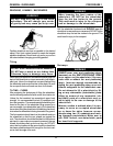
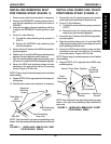
Angle Adjustment (FIGURES 4 AND 5)
1. Loosen, but do not remove the two (2) flat screws
and locknuts that secure footplate to the footplate
hinge.
2. Position the articulating footplate to the necessary
angle to accommodate the user.
3. Retighten the two (2) flat screws and locknuts.
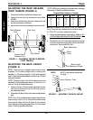
Footplate
Footrest Support
Side View Of
Footplate
and Footrest
Support.
FIGURE 5 - ANGLE ADJUSTMENT
F
R
O
N
T
R
I
G
G
I
N
G
S