


25
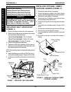
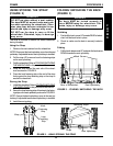
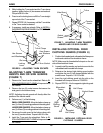
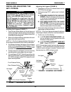
FIGURE 6 - ADJUSTING T-ARM SOCKETS
Hex Screws
and Washers
T-Arm
Hex Screws
and Washers
T-Arm Socket
T-Arm Clamp
Locking
Lever
Slot
5. While holding the T-arm socket and the T-arm clamp
together, tighten the four (4) hex screws and washers.
Torque to 80-90 in./lbs.
6. Press in on the locking lever and lift the T-arm straight
up and out of the T-arm socket.
7. Repeat STEPS 3-6, if necessary until the T-arm slides
in the T-arm socket as desired.
8. If necessary, install rear wheels. Refer to
INSTALL-
ING/REMOVING REAR WHEELS in PROCEDURE
7 of this manual.
A
R
M
S
PROCEDURE 6ARMS
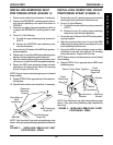
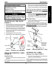
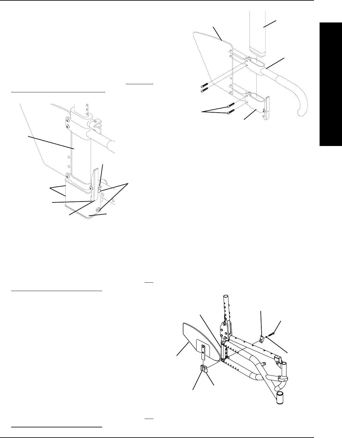
ADJUSTING T-ARM TRANSFER
ASSISTS AND/OR SIDE GUARDS
(FIGURE 7)
1. Remove the T-arm from the wheelchair. Refer to IN-
STALLING/REMOVING T-ARMS in this procedure of
the manual.
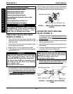
2. Remove the two (2) socket screws that secure the
side guard to the bottom clamp.
NOTE: Adjusting the side guards will directly affect the
position of the transfer assist.
3. Perform one (1) of the following:
SMALL SIDE GUARDS - Move the bottom clamp up
one (1) of two (2) mounting positions in the side guard.
LARGE SIDE GUARDS - Move the bottom clamp up
one (1) of three (3) mounting positions in the side guard.
4. Re-secure the side guard to the bottom clamp with
the two (2) socket screws. Torque to 80-90 in./lbs.
5. Install the T-arm onto the wheelchair. Refer to
IN-
STALLING/REMOVING T-ARMS in this procedure of
the manual.
Socket
Screws
Bottom Clamp
Transfer
Assist
Side Guard
T-Arm
FIGURE 7 - ADJUSTING T-ARM TRANSFER
ASSISTS AND/OR SIDE GUARDS
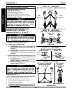
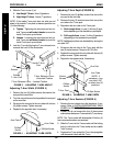
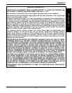
INSTALLING OPTIONAL RIGID
CLOTHING GUARDS (FIGURE 8)
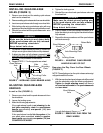
1. Position the threaded and unthreaded half clamps on
inside and outside of the wheelchair frame.
NOTE: Make sure the threaded half clamp is on the out-
side of the wheelchair frame.
2. Loosely install the washer and socket screw into the
unthreaded and threaded half clamps.
3. Determine the desired rigid clothing guard position
and tighten the two (2) half clamps together with the
socket screw. Torque to 110-120 in./lbs.
4. Insert the rigid clothing guard into the slot on the
threaded half clamp as shown in FIGURE 8.
5. Repeat STEPS 1-4 for the opposite rigid side guard.
FIGURE 8 - INSTALLING OPTIONAL RIGID
CLOTHING GUARDS
Threaded
Half Clamp
Washer
Wheelchair
Frame
Half Clamp
Socket Screw
Slot
Rigid
Clothing
Guard