


Q1-DC-0508
6
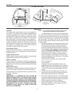
Electronic Expansion Valve (Optional)
A wide variety of electronic expansion valves and case
controllers can be utilized. Please refer to EEV and
controller Hussmann’s information sheet. Sensors for
electronic expansion valves will be installed on the coil inlet,
coil outlet, and in the discharge air. (Some supermarkets
require a 4th sensor in the return air). Case controllers will
be located in the electrical raceway or under the case.
Expansion Valve Adjustment
Expansion valves must be adjusted to fully feed the
evaporator. Before attempting any adjustments, make
sure the evaporator is either clear or very lightly covered
with frost, and that the xture is within 10°F of its expected
operating temperature.
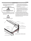
After case has been brought to running temperature
verify screws along glass clamp aluminum
extrusion are tight.
Measuring the Operating Superheat
1. Determine the suction pressure with an accurate
pressure gauge at the evaporator outlet.
2. From a refrigerant pressure temperature chart,
determine the saturation temperature at the
observed suction pressure.
3. Measure the temperature of the suction gas at the
thermostatic remote bulb location.
4. Subtract the saturation temperature obtained in step
No. 2 from the temperature measured in step No. 3.
5. The difference is superheat.
6. Set the superheat for 5°F - 7°F.
Thermostat Location
Thermostats are located in the electrical section; behind
the rear panel, on the right-hand side of the case (facing
the back of the case).
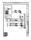
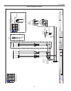
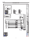
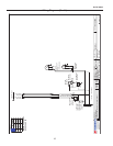
Electrical
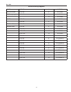
Wiring Color Code
CASE MUST BE GROUNDED
NOTE: Refer to label afxed to case to determine the actual
conguration as checked in the “TYPE INSTALLED”
boxes.
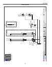
Electrical Circuit Identication
Standard lighting for all models will be full length uorescent
lamps located within the case at the top. The switch
controlling the lights, the plug provided for digital scale,
and the thermometer are located at the rear of the case
mullion.
The receptacle that is provided on the exterior back of these
models is intended for computerized scales with a ve amp
maximum load, not for large motors or other high wattage
appliances. It should be wired to a dedicated circuit.
BEFORE SERVICING
ALWAYS DISCONNECT ELECTRICAL
POWER AT THE MAIN DISCONNECT
WHEN SERVICING OR REPLACING ANY
ELECTRICAL COMPONENT.
This includes (but not limited to) Fans, Heaters
Thermostats, and Lights.
Field Wiring and Serial Plate Amperage
Field Wiring must be sized for component amperes printed
on the serial plate. Actual ampere draw may be less than
specied. Field wiring from the refrigeration control panel to
the merchandisers is required for refrigeration thermostats.
Case amperes are listed on the wiring diagram, but always
check the serial plate.
Ballast Location
Ballasts are located within the access panel that runs the
length of the rear of the case.
Refrigeration (Cont'd)