


Rev. 0508
5
Plumbing
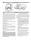
Waste Outlet and P-TRAP
The waste outlet is located off the center of the case on
one side allowing drip piping to be run lengthwise under
the xture.
A 1-1/2” P-TRAP and threaded adapter are supplied with
each xture. The P-TRAP must be installed to prevent air
leakage and insect entrance into the xture.
NOTE: PVC-DWV solvent cement is recommended. Follow the
Hussmann’s instructions.
Installing Condensate Drain
Poorly or improperly installed condensate drains can
seriously interfere with the operation of this refrigerator, and
result in costly maintenance and product losses. Please
follow the recommendations listed below when installing
condensate drains to insure a proper installation:
1. Never use pipe for condensate drains smaller
than the nominal diameter of the pipe or P-TRAP
supplied with the case.
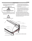
2. When connecting condensate drains, the P-TRAP
must be used as part of the condensate drain
to prevent air leakage or insect entrance. Store
plumbing system oor drains should be at least 14”
off the center of the case to allow use of the P-TRAP
pipe section. Never use two water seals in series in
any one line. Double P-TRAPS in series will cause a
lock and prevent draining.
3. Always provide as much down hill slope (“fall”) as
possible; 1/8” per foot is the preferred minimum.
PVC pipe, when used, must be supported to
maintain the 1/8” pitch and to prevent warping.
4. Avoid long runs of condensate drains. Long runs
make it impossible to provide the “fall” necessary for
good drainage.
5. Provide a suitable air break between the ood rim of
the oor drain and outlet of condensate drain. 1” is
ideal.
6. Prevent condensate drains from freezing:
a. Do not install condensate drains in contact with
non-insulated suction lines. Suction lines should
be insulated with a nonabsorbent insulation
material such as Armstrong’s Armaex.
b. Where condensate drains are located in dead
air spaces (between refrigerators or between a
refrigerator and a wall), provide means to prevent
freezing. The water seal should be insulated to
prevent condensation.
Refrigeration
Refrigerant Type
The standard refrigerant will be R-22 unless otherwise
specied on the customer order. Check the serial plate on
the case for information.
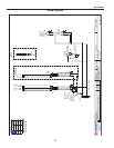
Piping
The refrigerant line outlets are located under the case.
Locate rst the electrical box, the outlets are then on the
same side of the case, but at the opposite end. Insulate
suction lines to prevent condensation drippage.
Refrigeration Lines
Liquid Suction
3/8” O.D. 5/8” O.D.
NOTE: The standard coil is piped at
1
/
2
” (suction); however,
the store tie-in may vary depending on the number of
coils and the draw the case has. Depending on the case
setup, the connecting point in the store may be
5
/
8
”,
7
/
8
”,
or 1
1
/
8
”. Refer to the particular case you are hooking up.
Refrigerant lines should be sized as shown on the
refrigeration legend furnished by the store. Install P-TRAPS
(oil traps) at the base of all suction line vertical risers.
Pressure drop can rob the system of capacity. To keep the
pressure drop to a minimum, keep refrigerant line run as
short as possible, using the minimum number of elbows.
Where elbows are required, use long radius elbows only.
Control Settings
See Q1-DC technical data sheet for the appropriate
settings for your merchandiser. Maintain these parameters
to achieve near constant product temperatures. Product
temperature should rst be measured in the morning, after
having been refrigerated overnight. For all multiplexing,
defrost should be time terminated. Defrost length and
frequency should be as directed in the Q1-DC technical
data sheet. The number of defrosts per day should never
change. The duration of the defrost cycle may be adjusted
to meet conditions present at your location.
Access to TEV Valves and Drain Lines
MECHANICAL - Remove product from case. Remove
pans. TX valve (mechanical only) and drain are located
under the pans within the case.
ELECTRONIC - The electronic expansion valve master and
slave cylinder(s) are located within the electrical access
panel(s) in the rear of case. Rear panels lift up and out.
NOTE: Duplex receptacles must be detached before removing
rear panels.