


Boiler
Installation
If
the
controller
is
being
used
on
a
boiler
installation
test
it
as
follows
1
Note
the
boiler
pressure
by
checking
the
boiler
pres
sure
gauge
To
perform
this
testproperly
the
boiler
should
have
a
pressure
reading
near
the
middle
of
the
controller
s
main
scale
range
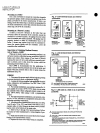
2
Turn
the
main
scale
adjusting
screw
Fig
11
until
the
m
rlnscale
setting
indicator
on
the
controller
corresponds
to
th
b9iler
pressure
gauge
readiri
g
3
TheL404A
or
C
should
break
the
control
circuit
s
automatically
when
the
boiler
pressure
gauge
reading
equals
or
slightly
exceeds
the
controller
setting
The
L404B
or
D
should
make
the
circliit
under
the
same
circumstances
The
L404F
L604L
M
should
inake
the
R
W
circuit
and
break
the
R
B
circuit
under
the
same
circumstances
The
L604A
should
make
the
RI
W
circuit
and
break
the
R2 B
circuit
under
the
same
circumstances
4
If
the
controller
is
operating
properly
turn
the
main
scale
adjusting
screw
Fig
11
until
the
main
scale
setting
indicator
is at
the
desired
set
point
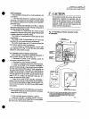
If
a
Controller
Seems
to
Operate
Improperly
If
the
controller
is
suspected
of
operating
iniproperly
it
may
be
further
checked
as
follows
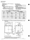
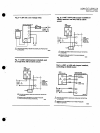
Fig
12
1
Disconnect
all
power
to
the
controller
loosen
the
cover
screw
and
remove
the
cover
2
DisconneCt
the
wires
from
the
controller
3
Connect
an
ohmmeter
between
the
switch
terminals
4
Lower
the
set
point
of
the
controller
simulating
a
pressure
increase
through
a
range
greater
than
the
differen
tial
The
switch
should
either
make
or
break
depending
on
the
model
of
the
controller
AnL404A
orC
should
break
an
L404B
or
D
should
make
an
IA04F
L604L
M
should
break
R
B
and
make
R
W
and
an
L604A
should
breakR2
B
and
make
RI
W
If
it
makes
the
ohmmeter
reads
zero
if
it
breaks
the
ohmmeter
reads
infinity
5
Raise
the
set
point
of
the
controller
simulating
a
pressure
decrease
through
a
range
greater
than
the
differen
tial
The
switch
should
break
or
make
just
the
opposite
of
its
action
in
step
4
except
for
the
L404C
D
and
L604L
manual
reset
models
NOTE
An
approximation
of
the
differential
can
be
made
by
observing
the
change
in
set
point
required
for
a
resistance
change
from
zero
to
infinity
6
If
the
controller
operates
improperly replace
it
7
When
the
controller
is
operating
properly
reconnect
the
wires
to
the
terminal
block
replace
the
cover
and
tighten
the
cover
screw
and
reconnect
the
power
L404A
D
F
L604A
L
M
SETTING
AND
CHECKOUT
ffi
CAUTION
Do
not
put
the
system
into
service
until
you
have
satisfactorily
completed
all
applicable
tests
de
scribed
in
this
Checkout
section
in
the
Checkout
section
of
the
applicable
instructions
for
the
flame
safeguard
control
and
any
others
required
by
tlie
burner
and
boiler
manufacturers
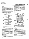
Fig
12
Checking
controller
operation
using
an
ohmmeter
MAIN
SCALE
SETllNG
INDICATOR
00
INPUT
OUTPUT
o
280
ADJ
MAIN
SCALE
ADJUSTlNG
SCREW
I
I
I
I
I
I
I
I
I
I
I
I
I
I
I
I
I
I
I
ro
SETPOINT
DEqREASE
ZERO
OHMS
INANITY
WHEN
R
B
BREAKS
AN
l
604
WITH
JUMPER
INSTALLED
BElWEEN
Rl
AND
R
IS SHOWN
AN
L404F
OPERATES
SIMIlJ
RL
Y
SPOT
SWITCHING
AN
L404A
B C
OR
0
HAS
ONLY
TWO
TERMINALS
SPST SWITCHING
AN
L404A
OR
C
BREAKS
AND
L404B
OR
0
MAKES
WHEN
THE
SETPOINT
IS
DECREASED
FAfl
ENOUGH
M8944