


L404A
D
F
L604A
L
M
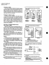
INSTALLATION
Mounting
on
a
Boiler
If
it
is
not
convenient
to
mount
the
controller
alongside
the
pressure
gauge
install
a
steam
trap
siphon
loop
in
the
fitting
provided
by
the
boiler
manufactUrer
If
there
is
no
fitting
mount
the
steam
trap
at
a
location
recommended
by
the
boiler
manufacturer
Screw
the
controller
directly
to
the
steam
trap
and
level
the
controller
Mounting
at
a
Remote
Location
If
there
is
excessive
vibration at
the
boiler
that
can
adversely
affect
the
operation
of
the
controller
mount
the
controller
at
a
remote
location
All
piping
from
the
boiler
must
be
suitable
and
solidly
mounted
The
piping
must
be
properly
pitched
to
drain
all
condensation
back
to
the
boiler
A
steam
trap
siphon
loop
must
be
mounted
be
tween
the
remote
piping
and
the
controller
Level
the
controller
after
installation
Supervision
of
Atomizing
Medium
Pressure
Air
or
Steam
L404B
When
air
or
steam
is used
as
an
atomizing
medium
in
an
oil
burner
system
authorities
having
jurisdiction
approval
bodies
and
codes
often
require
a
low
limit
to
prevent
opening
the
main
oil
valve
until
sufficient
atomizing
pres
sure
is
present
and
to
shut
down
the
system
when
the
atomizing
pressure
falls
too
low
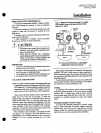
The
L404B
is
recommended
for
this
application
It
makes
a
circuit
when
the
pressure
rises
to
the
set
point
and
breaks
when
the
pressure
falls
to
the
set
point
minus
the
differential
Fig
10
WlRING
1
DiscoDDe
t
the
power
supply
before
beginning
wiring
to
preventelectrical
shock
or
equipment
damage
2
Assume
all
wiring
complies
with
applicable
electrical
co
ordinances
and
regulations
Use
NEC
Class 1
line
voltage
wiring
3
Fornormalinstallations
use
moisture
resistant
No
14
wire
sUitable
for
at
least
1670
1
750C
when
you
are
using
the
controller
with
a
flame
safeguard
primary
control
or
at
least
1940F
900C
when
using
it
with
a
programming
control
4
For
high
temperature
installations
use
moisture
resis
tant
No
14
wire
selected
for
a
temperature
rating
above
the
maximum
operating
temperature
5
All
models
have
a
terminal
block
inside
the
cover
Fig
3
and
4
and
a
7 8
in
22
2
mm
hole
in
one
side
for
1
2
in
condui
cable
or
wires
Remove
the
front
cover
by
loosen
ing
tIi
e
screw
at
the
bottom
of
the
main
scale
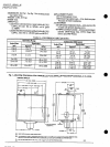
6
Refer
to
Fig
5
through
9
for
typical
hookups
Follow
the
burner
or
boiler
manufacturer
s
wiring
diagram
if
pro
vided
7
Make
sure
the
loads
do
not
exceed the
Switch
Contact
Ratings
in
the
Specifications
section
8
Replace
the
front
cover
when
wiring
is
completed
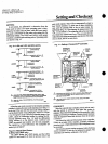
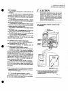
Fig
3
L404
terminal
blocks
and
internal
schematics
RISE
L404A
C
L404B
D
BREAKS
ON
PRESSURE
RISE
TO
SETPOINT
MAKE ON
PRESSURE
RISE
TO
SETPOINT
RISE
B
L404F
SNAP ACTING
BREAKS
R
a
MAKES
R
WON
PRESSURE
RISE
TO
SETPOINT
M8941
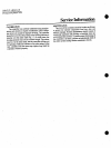
Fig
4
L404
terminal
block
and
Internal
schematic
L604A
L604L
M
MAKES
Rl
W
BREAKS
R2
8
ON
PRESSURE RISE
TO
SETPOINT
SPDT
SWITCH
ACTION
WITH
JUMPER
INSTALLED
M8935
OTHERWISE
TWO
ISOLATED
SPST SWITCHES
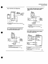
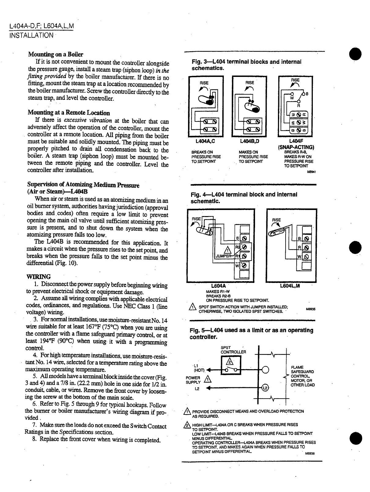
Fig
S
L404 used
as
a
limit
or
as
an
operating
controller
SPST
CONTROLLER
Ll
HOT
POWER
1
SUPPLY
Lll
U
FlAME
SAFEGUARD
CONTROL
MOTOR
OR
OTHER
LOAD
PROVIDE
DISCONNECT
MEANS
AND
OVERLOAD
PROTECTION
AS
REQUIRED
HIGH
UMIT
l
404A
OR
C
BREAKS
WHEN
PRESSURE
RISES
TO
SETPOINT
LOW
UMIT
t
4048
BREAKS WHEN
PRESSURE
FALLS
TO
SETPOINT
MINUS
DIFFERENTIAL
OPERATING
CONTROLLER
t
404A
BREAKS
WHEN
PRESSURE
RISES
TO
SETPOINT AND
MAKES
AGAIN WHEN
PRESSURE
FALLS
TO
SETPOINT
MINUS
DIFFERENTIAL
M8936