


l404A
D
F
l604A
l
M
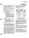
INSTALLATION
Installation
WHEN
INSTALLING
TIllS
PRODUCT
1
Read
these instructions
carefully
Failure
to
follow
them
could
damage
the
product
or
cause
a
hazardous
condition
2
Check
the
ratings
given
in
the
instructions
and
on
the
prod
ct
to
make
sure
the
product
is
suitable
for
your
application
3
Installer
must
be
a
tramed
expenenced
flame
safe
guard
control
technician
4
After
installation
is
complete
check
out
product
operation
as
provided
in
these
instructions
ffi
CAUTION
1
Disconnect power
supply
before
beginning
in
stallation
to
prevent
possible
equipment
dam
age
or
electrical
shock
2
When
using
the
controller
with
a
compressor
install
a
dampening
device
such
as
aneed1e
valve
header
or
surge
tank
to
dampen
pulsations
that
can
damage
the
controller
or
reduce its
life
IMPORTANT
1
Locate
the
controller
where
the
ambient
temperature
will
not
exceed
1500F
660C
2
Use
pipe
compound
sparingly
to
avoid
clogging
the
hole
in
the
pipe
or
diaphragm
fitting
3
Do
not
tighten
the
controller
by
hand
by
holding
the
case
4
Accurately
level
the
controller
for
proper
operation
LOCATION
AND
MOUNTING
NOTE
For
most
accurate
operation
add
supplemental
heat
to
installations
where
the
temperature
falls
below minus
200P
minus 290C
Never
locate
the
controller
where
the
temperatUre
falls
below
minus
350P
minus
370C
be
cause
mercury
in
the
switch
freezes
at
this
temperature
When
used
with
steam
boilers
always
mount
the
con
troller
above
the
water
line in
the
boiler
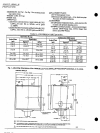
A
steam
trap
siphon
loop
must
always
be
connected
between
the
con
troller
and
the
boiler
Fig
2
to
prevent
boiler
scale and
corrosive
vapors
from
attacking
the
diaphragm
The
loop
on
the
steam
trap
must
always
be
perpendicular
to
the
face
of
the
controller
If
the
loop
is
parallel
to
the
controller
expansion
or
contraction
of
the
loop
tips
the
controller
and
causes
the
switch
to
operate
inaccurately
The
controller
can
be
mounted
1
alongside
the
pres
sure
gauge
2
in
a
fitting
on
the
boiler
provided
by
e
manufacturer
3
at
a
remote
location
in
case of
excesSIve
vibration
or
4
in
a
special
mounting
on
a
low
water
cutoff
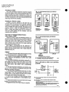
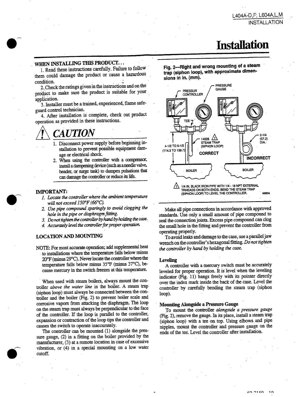
Fig
2
Rlght
and
wrong
mounting
of
a
steam
trap
siphon
loop
with
approximate
dimen
sions
in in
mm
1
4
IN
BLACK
IRON
PIPE
WITH
1
4
18
NPT
EXTERNAL
TRHEADSON
BOTH
ENDS
BEf
lD
THE
STEAM
TRAP
SIPHON
LOOP
TO
LEVEL
THE
CONTROLLER
M8934
Make
all
pipe
connections
in
accordance
with
approved
standards
Use
only
a
small
amount
of
pipe
compound
to
seal
the
connection
joints
Excess
pipe
compound
can
clog
the
small
hole
in
the
fitting
and
prevent
the
controller
from
operating
properly
To avoid
leaks
and
damage
to
the
case
use
a
parallelJaw
wrench
on
the
controller
s
hexagonal
fitting
Donot
tig
ten
the
controller
by
hand
by
holding
the
case
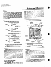
LeveUng
A
controller
with
a
mercury
switch
must
be
accurately
leveled
for
proper
operation
It
is
level
when
the
leveling
indicator
Fig
11
hangs
freely
with
its
pointer
directly
over
the
index
mark
inside
the
back
of
the
case
Level
the
controller
bycarefu11y
bending
the
steam
trap
siphon
loop
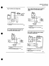
Mounting
Alongside
a
Pressure
Gauge
To
mount
the
controller
alongside
a
pressure
gauge
Fig
2
remove
the
gauge
In
its
place
install
a
steam
ap
siphon
loop
with
a
tee
on
top
Using
elbows
and
pIpe
nipples
moUnt
the
controller
and
pressure gau
e
on
the
ends
of
the
tee
Level
the
controller
after
installattOn
I
11