


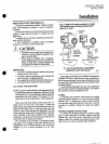

04A
D
F
L604A
L
M
ETTING
AND
CHECKOUT
Setting
and
Checkout
SETIING
In
all
models
the
differential
is
subtractive
from
the
main
scale
set
point
The
upper
operating
point
is
deter
mined
by
the
main
scale
set
point
while
the
lower
operat
ing
point
is
determined
by
the
main
scale
setting
less
the
differential
setting
The
L404F
and
L604A
with
jumper
installed
L
M
have
spdt
switching
action
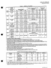
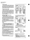
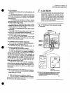
Operating points
are
shown
in
Fig
10
Fig
1o
L404
and
L604
operating
points
L404A
C
PRESSURE
RISE
I
MAIN SCALE
SETPOINT
SWITCH
BREAKS
SUBTRACTIVE
DIFFERENTIAL
DIFFERENTIAL
SETTING
SWITCH
MAKES
L404B
D
PRESSURE
RISE
I
MAIN
SCALE
SETPOINT
SWITCH
MAKES
SUBTRACTIVE
DIFFERENTIAL
DIFFERENTIAL
SETTING
4
SWITCH
BREAKS
ill
MAIN
SCALE
SETPOINT
4
BREAKS
RB
MAKES
R
W
ill
SUBTRACTIVE
DIFFERENTIAL
L404F
L604
M
PRESSURE
RISE
I
DIFFERENTIAL
SETTING
a
MAKES
RB
BREAKS
R
W
L604A
MAIN SCALESETPOINT
MAKE
Rl
W
BREAKS
R2
8
SUBTRACTIVE
DIFFERENTIAL
PRESSURE
RISE
DIFFERENTIAL
SETTING
BREAKS
Rl W
MAKES
R2
8
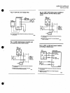
lA04C
D
AND
l604L
MANUAL
RESET
MeDB
S
HAVE
A
SMALL
AXED
DIFFERENTIAL
THEY
CAN
BE
MANUALLY
RESET
WHEN
THE
PRESSURE
FALLS
TO
THE
MAIN
SCALE
SETPOINT
MINUS
THE
DIFFERENTlAL
l
604M
HAS
A
SMALl
AXED
DIFFEAENTlAL
OF
3 5
PSI
0
25
kgIcm2
W
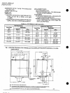
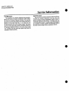
Adjust
the
main
scale
set
point
for
the
desired
operating
pressure
by
turning
the
main
scale
adjusting
screw
Fig
11
on
the
top
of
the
case
until
the main
scale
setting
indicator
is
at
the
desired
value
On
an
L404A
B F
with
a
5
to
150
psi
2
3
to
10
3
kg
cm
34
to
1034
kPa
operating
range
or
an
L604A
adjust
the
differential
setting
by
turning
the
dif
ferential
adjusting
screw
Fig
11
until
the
differential
setting
indicator
is at
the
desired value
L404C
D
and
L604L
are
manual
reset
models
see
the
next
paragraph
The
L604M
has
a
fixed
differential
The
scaleplates
are
marked
psi
arid
kg
cm2
Trip
Free
Manual
Reset
Feature
L404C
D
and
L604Lonly
The
L404C
breaks
the
L404D
makes
and
the
L604L
makes
R
W
and
breaks
R
B
when
the
pressure
rises
to
the
main
scale
setpoint
They
will
not
automatic
illy
return
to
their
fonner
positions
To
reset
one
of
these
controllers
wait
until
the
pressure
falls
to
the
set
point
minus
the
differential
Fig
10
Then
depress
the
manual
reset
lever
Fig
11
and
release
it
The
controller
will
not
be
reset
until
you
release
the
manual
reset
lever
This
prevents
the
con
troller
from
becoming
an
automatic
reset
device
if
the
reset
lever
is
stuck
held
in
or
tied
down
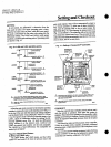
Fig
11
Setting
a
Press
Jretrollli
Controller
DIAPHRAGM
ASSEMBLY
INDICATOR
ADJUSTABLE
DIFFERENTIAL
ON
THE
L404A
B
F
L404L
WITH
A
5
TO
150
PSI
0
34
TO
103
kglcm2
34
TO
134
kPal
OPERATING
RANGE
AND
L604A
MODELS
ONLY
TRIP
FREe
MANUAL
RESET LEVER
ON
THE
L404C
D
AND
L604L
MODELS
ONLY
MIlIl43
CHECKOUT
After
the
controller
has
is installed
wired
and
set
test
it
with
the
system
in
operation
First
allow
the
system
to
stabilize
Then
observe
the
operation
of
the
controller
while
raising
and
lowering
its
setpoint
Pressure
should
increase
when
the
setpoint
is
raised
and
decrease
when
the
set
point
is
lowered
Also
check
the
make
and
break
points
of
the
controller
If
they
do
not
agree
with
a
separate
accurately
calibrated
pressure
gauge
a
slight
adjusnnent
of
the
scaleplate
s
may
be
necessary
Use
accurate
pressure
testing
equipment
when
checking
out
the
controller
Do
not
rely
on
inexpensive
gauges
The
controllers
are
carefully
calibrated
at
the
factory