


SKU 47591 Page 7
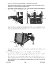
13. Disconnect the positive (red) cable to the vehicle battery.
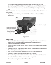
You will now be making an electrical connection from the Motorized Cable Module
(27) to the vehicle electrical system.
Caution: Although the 12 VDC battery cannot shock you, it can spark and heat up cables
to the melting point, and can cause burns, if not installed and fused correctly. That is
why the battery is disconnected at this time.
14. Locate an appropriate positive (+ / red), fused, 50 amp terminal point on the vehicle
able to supply the 45 amps of current the lift will be drawing at full load.
If vehicle is already wired with a rear, 12 volt connector, the lift may be connected
here with the appropraite connector ( not supplied). The circuit MUST BE ABLE
TO HANDLE the Hitch Lift’s 45 amp draw and must be fused at 50 amps. YOU
SHOULD CHECK your vehicle’s owner’s manual or consult with the auto dealer to
ensure that the vehicle’s electrical circuit is capable of handling this kind of current
load.
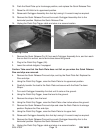
15. Route the cables, making sure that you leave enough cable to plug the connector
into the Motorized Cable Module (#27). Also route cable away from any hot spots
(muffler, catalytic converter) or any area where the cable may be pinched or cut.
16. If vehicle has an existing spare 50 amp fused terminal point, simply connect the
supplied positive cable directly to the fused terminal point.
17. If the vehicle as no 50 amp terminal point, the customer will need to install a 50 amp
circuit breaker (not included) in line between the battery and Hitch Lift. The circuit
breaker should be installed as close to the battery as possible. The RED cable will
need to be cut and the two 6 AWG battery terminals installed into the ends of
the cable. The short end of the cut cable should be long enough to reach the battery
terminal. Connect one end of the cable to a circuit breaker post. Now connect the
other cable end to the other post.
AT THIS TIME, DO NOT CONNECT THE CABLE TO THE BATTERY!!
18. Connect the black negative (-) cable to the vehicle’s metal frame, or a ground lug on
or near the battery.
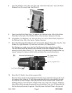
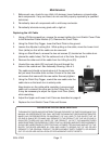
19. Reconnect the red positive (+) battery cable to the battery.
20. Plug the Lift Hitch Battery Cable (23) connector plug into the Motorized Cable Module.
It is located under the module. See photo F.
21. Plug the Pistol Grip Trigger (24) cable plug into the Motorized Cable Module.
REV 08/02
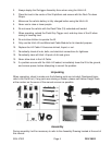
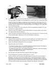
If no fused, 50 amp terminal point is provided, you will need to provide a separate
circuit (fused at 50 amps) directly from the battery. The customer will need to pro-
vide one (1) 50 amp circuit breaker and two (2) 6 AWG battery terminals with 5/16”
opening.