


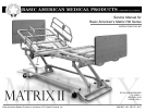
2D:4>6C:42?#65:42=&C@5F4ED25:G:D:@?@762=E9&C@5F4ED?4
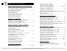
ABLE OF CONTENTS
T
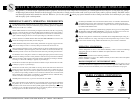
safety information and specifications
safety & warning information . . . . . . . . . . . . . . . . . . . . . . . 1
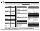
entrapment compliance information . . . . . . . . . . . . . . . . 2
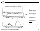
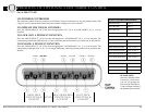
bed features & specifications . . . . . . . . . . . . . . . . . . . . . . . . . 3
• Features & Mechanical Dimensions
• Electrical Specifications
• Available Options/Accessories
bed positioning specifications . . . . . . . . . . . . . . . . . . . . . . . . 4
• Maximum High and Low Bed Positions
• Maximum Head/Back Elevation/Angle
• Maximum Knee/Foot Elevation/Angle
operating your bed
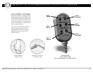
operation - std. pendant/hand controller . . . . . . . . . . 5
• Pendant Diagram and Operational Instructions
operation - opt. staff/nurse control . . . . . . . . . . . . . . . . . 6
• Staff Diagram and Operational Instructions
board assembly & Misc. features
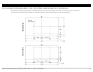
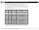
standard head- & footboards . . . . . . . . . . . . . . . . . . . . 7 - 10
• Std. Head- & Footboard Boring Patterns
• Assembly Instructions
• Head- & Footboard Assembly Parts
• Head- & Footboard Assembly Diagram
optional embedded staff control . . . . . . . . . . . . . . . . . . . . 11
• Assembly Instructions
• Footboard Embedded Control Parts & Diagram—single control box
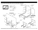
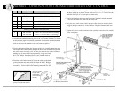
standard & optional wallsavers . . . . . . . . . . . . . . . . . . . . . 13
• Assembly Instructions
• Standard Wallsaver & Side Wallsaver Assembly Parts
• Wallsaver Assembly Diagrams
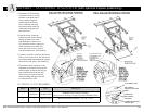
standard mattress retainers . . . . . . . . . . . . . . . . . . . . . . . . 14
• Assembly Instructions
• Mattress Retainer Assembly Parts & Diagram
OPTIONAL edema foot ratchet . . . . . . . . . . . . . . . . . . . . . . . . 15
• Edema Diagram and Operational Instructions
accessories assembly
Head & foot half-rails . . . . . . . . . . . . . . . . . . . . . . . . . . . 17 & 18
• Diagram, Parts, and Assembly Instructions
Foot rail bracket assembly . . . . . . . . . . . . . . . . . . . . . . . . . . 19
• Diagram, Parts, and Assembly Instructions
Head & foot assist bars/rails . . . . . . . . . . . . . . . . . . . . 20 & 21
• Diagram, Parts, and Assembly Instructions
standard 4” extension pan . . . . . . . . . . . . . . . . . . . . . . . . . . 22
• Diagram, Parts, and Assembly Instructions
optional 42” wide deck & Wide deck ext. pan . . . 23 & 24
• Diagram, Parts, and Assembly Instructions
trapeze support . . . . . . . . . . . . . . . . . . . . . . . . . . . . . . . . . . . . . . 25
• Diagram, Parts, and Assembly Instructions
bed parts and hardware
Head, Knee & foot decks to main frame . . . . . . . . . . . . . 27
• Diagram, Parts, and Assembly Instructions
main frame to u-levers AND DRAG LINK . . . . . . . . . . . . . . 28
• Diagram, Parts, and Assembly Instructions
LOWER u-levers to standard caster carriage . . . . . . . 29
• Diagram, Parts, and Assembly Instructions
LOWER u-levers to lock caster carriage w/m-lok . . . 30
• Diagram, Parts, and Assembly Instructions
electronics & cabling
head motor to head deck and main frame . . . . . . . . . 32
• Diagram, Parts, and Assembly Instructions
foot motor to knee deck and main frame . . . . . . . . . . 33
• Diagram, Parts, and Assembly Instructions
hi/lo motorS to drag linkS and u-leverS . . . . . . . . . . . . 34
• Diagram, Parts, and Assembly Instructions
control box connections & cabling . . . . . . . . . . . . . . . . 36
• Diagram, Parts, and Connection Instructions
Head, Foot, and Hi/Lo cable routing . . . . . . . . . . . . . 37 - 39
• Diagram and Routing Instructions
pendant cable & power cord routing . . . . . . . . . . 40 & 41
• Diagram and Routing Instructions
miscellaneous
electronic troubleshooting . . . . . . . . . . . . . . . . . . . . . . . . 42
recommended service and maintenance . . . . . . . . . . . . . 43
notes . . . . . . . . . . . . . . . . . . . . . . . . . . . . . . . . . . . . . . . . . . . . . . . . . 44