


2D:4>6C:42?#65:42=&C@5F4ED25:G:D:@?@762=E9&C@5F4ED?4K#2EC:IK(,#2?F2= &
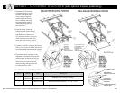
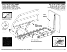
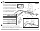
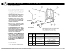
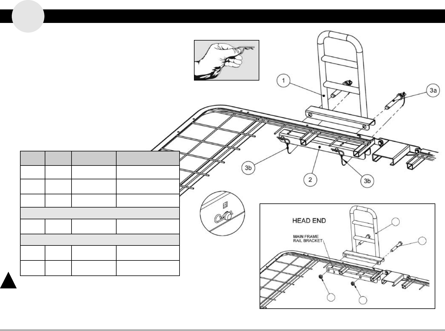
Item # Qty. Part # Description
1 1 999-0803-902G Assist Bar - Head End
2 1 -
Head Deck Rail Bracket
(pre-welded on deck)
not
shown
2 100-4710-003 1.00” Dia. End Caps
Quick Release Option 1 (in Hdw Bag 999-0803-905)
3 2 999-0784-100
Quick Release
Lanyard Assembly
Fixed Attachment Option 2 (in Hdw Bag 999-0803-905)
4 2 100-5463-004
5/8-11 x 4.50”
Hex Head Cap Screw
5 2 100-6763-001
5/8-11 Thin Nylon
Lock Nut
ccessory Assembly - HEAD-END ASSIST BAR
A
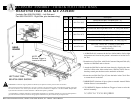
WARNING: The mattress support platform should always be placed in the flat position when not attended.
When assessing the Risk for Entrapment, you need to consider your bed, mattress, head- and footboards,
half rails, assist bars, and other accessories as an entire system. All bed systems are evaluated for compliance
to the FDA/CDRH “Hospital Bed System Dimensional and Assessment Guidance to Reduce Entrapment” guidelines.
A resident/patient’s condition could lead to resident/patient entrapment. It is extremely important to review the resident/
patient’s physical and mental condition, and initiate an appropriate individual care plan to address any entrapment risks.
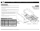
!
%&*%$N
%&*%$N
1
4
5
5
=@D6FA@72:C
&:?=:A
:?D6CE65:?E@
9@=6:?=6G:D
&:?
*@D276=JC6>@G62:C&:?=:A
8C2DA@?4:C4F=2C6?52?5AF==
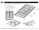
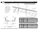
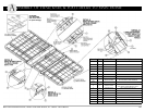
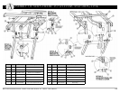
1. With the Assist Bar (#1) bracket facing inward toward the bed as
shown, align the two holes on the bracket with the first and third
holes (from the head-end of the bed) of the pre-welded head deck
bracket (#2)
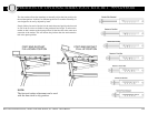
2. For the quick release option, insert the Clevis Pin end of the two
Lanyard assemblies (3a) from the outside into the assist bar bracket
holes. Insert the hair pins on the opposite end of the lanyard
assemblies (3b) into the holes of the clevis pins.
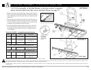
3. For a fixed attachment option, insert two cap screws (#4) from
the outside into the assist bar bracket holes. Secure the
screws by attaching two Thin Nylon Lock Nuts (#5).
Tighten with two 13/16 wrenches.
:./:3<*