


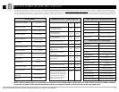
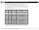
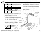
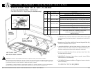

Item # Qty Part # Description
" #!
1 1 Z53650 Std. Oak Head- & Footboard (with cut out)
2 1 999-0775-901 Staff Control Assembly with Cables
3 1 999-0775-006G Wide Staff Control Shroud
4 6 100-5506-002 #6 x .50” Phillips Truss Head Screws (Blk)
5 3 100-1100-024 4” Nylon Cable Tie
Mounting Tube to Main Frame Hardware
6 2 100-7931-007 5/16 x 1.50” Clevis Pin w/hole (existing)
7 2 100-2001-006 1-9/16 x .072 Hair Pin Clip (existing)
2D:4>6C:42?#65:42=&C@5F4ED25:G:D:@?@762=E9&C@5F4ED?4K#2EC:IK(,#2?F2= &
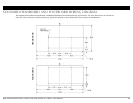
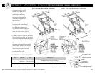
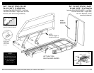
1. Assemble the footboard mounting tubes to the “staff control footboard” as shown
on the previous pages if not already assembled. Note that the standard footboard
does not have the cut outs for the staff control assembly. A separate footboard
with cut outs must be ordered for the staff controller option.
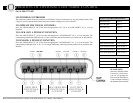
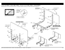
2. Facing the footboard from the foot-end of the bed, carefully thread the male
and female staff control cables through the hole in the footboard and position
the staff control assembly (#2) into the pre-formed slot on the footboard,
making sure all screw holes line up correctly. Using two black
#6 X .50” Phillips Truss Head Screws (#4), from the back of
the footboard secure the Staff Control via the outermost holes.
3. Place the Staff Control Shroud (#3) over the cables on the back
of the footboard and attach with four black #6 X .50” Phillips
Truss Head Screws (#4). Lightly tighten all screws with a phillips
screwdriver. Tie the cables to the mounting tubes with ties (#5).
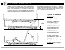
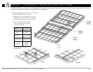
4. Insert the Footboard Mounting Tubes into the Main Bed Frame Tubes so that
the holes match up as shown. Secure with two 5/16 x 1-1/2” Clevis Pins (#6)
and Hair Pin Clips (#7) (1 each per bed frame tube).
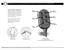
5. Unplug the Pendant cable from the Extension Cable that’s already attached
to the left side frame rail at the foot end of the bed.
6. Plug the male staff control cable into the cable extension that has been
plugged into the control box in the HB Port. Plug the Pendant cable into
the female staff control cable.
7. Tighten all screws on the Footboard with a phillips screwdriver. Be careful
not to overtighten.
ssembly - OPTIONAL foot board EMBEDDED STAFF CONTROL
A
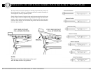
=@D6FA@72:C
&:?=:A
:?D6CE65:?E@
9@=6:?=6G:D
&:?
*@D276=JC6>@G62:C&:?=:A
8C2DA@?4:C4F=2C6?52?5AF==
Tools Needed:
(1) Phillips Screwdriver