


Alante´ GP201 Manual Revised 060208
31
DIAGNOSTICS/TROUBLESHOOTING
The joystick controller LED display is designed to help you diagnose any
problems with the electrical components of your power chair. The LED
display does this by flashing on and off in a coded sequence. Below is a
list of trouble-shooting actions. Try to use this list before you contact
your Golden Technologies representative. Go to the number in the list
which matches the number of flashing bars and follow the instructions.
If the problem persists after you made the checks described, contact your
Golden Technologies representative for further assistance.
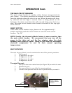
Flash Codes indicate the nature of an abnormal condition directly from
the A-Series Information Gauge. Without the use of any servicing tools,
the condition can be simply diagnosed.
Flash
Code
Description
1 User Fault Possible stall timeout or user error.
Release the joystick controller to
neutral and try again.
2 Battery Fault Check the batteries and cabling. Try
charging the batteries. Battery may
require replacement.
3 Left Motor Fault Check the left motor, connections and
cabling.
4 Right Motor Fault Check the right motor, connections
and cabling.
5 Left park brake fault Check the left park brake,
connections and cabling.
6 Right park brake fault Check the right park brake,
connections and cabling.
7 User Interface Fault Display PCB fault. Consult service
agent.
8 Joystick controller Fault Consult service agent.
9 A-Series Bus
Communications Fault
Consult service agent.
DIAGNOSTICS
Controllers are not user serviceable. Specialized tools are necessary
for the repair of any A-Series component.
A flashing A-Series Information Gauge indicates there is an
abnormal condition somewhere on the power chair. The
components that A-Series provides fault information for include the
motors, the park brakes, the batteries, the cabling and the A-Series
modules themselves.