


50
Chapter 6: Maintaining Your Filtered Enclosure
Calibrate and Operate the Airflow
Monitors
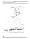
Guardian Airflow Monitor (LED Monitor)
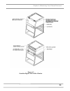
Refer to Figure 6-2 for operation and calibration.
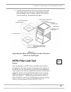
Labconco Airflow Monitor / Airflow Switch Operation
The Guardian Airflow Monitor (LED) consists of a circuit board
and an airflow switch. This switch indicates airflow as safe or low.
It does not provide an actual face velocity, but a small setscrew in
the back of the sensor can adjust the airflow level that it classifies
as “good/safe” or “low/alert.”
The circuit board provides power to the sensor and also contains a
“safe (green)” and “alert (red)” airflow LED indicators, as well as
a “SILENCE ALARM” button to quiet the audio alarm. When
first powered up, the PCB will light both red and green LED
indicators and sound the alarm to indicate it is working. After 5
seconds, the air monitor will indicate either good or bad airflow
based on what the connected airflow switch detects. For low
airflow, the unit will wait for 10 seconds of bad indications before
it sounds both the audio alarm and the red “alert” LED indicator.
If the “SILENCE ALARM” button is pressed, the audio alarm will
be silenced, but the red “alert” LED will remain on. The alarm is
silenced indefinitely unless an airflow change is detected. If safe
airflow is later detected for 10 seconds, the green “safe” LED will
be lit and the “alert” (red) LED will be shut off. At any time the
airflow is safe/good, one can press the SILENCE ALARM test
button and the audio alarm and the red LED will turn on as long as
this button is held down. The PCB has also a two-pin connector
for use as an external output with isolated relay contacts that close
when the red/alert LED is lit (low airflow). These relay contacts
are not affected by the “SILENCE ALARM” button.
The PCB is mounted behind the front panel using standoffs and an
appropriate label is used to highlight the “SILENCE ALARM”
button with clear areas for the red and green LED’s. No holes to
allow sound to be broadcast louder are necessary.
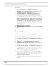
The PCB can be prepared as a factory special with an additional
connector for the following external inputs, and having the
following possible functions:
OPTION