


49
Chapter 6: Maintaining Your Filtered Enclosure
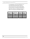
8. If necessary, adjust the speed control of the enclosure to
maintain the following airflows at 90 fpm; 2' (130cfm), 3' (200
cfm, 4' (265 cfm.)
9. Position the aerosol generator discharge in the intake of the
baffle inside the enclosure.
10. Start the aerosol generator (Pressure to be +/- 1 PSIG). Ensure
that one Laskin nozzle is in the “open” position.
11. Allow the generator to operate for a minimum of 15 seconds.
For all integral motorized impeller models, scan the
downstream exhaust side of the HEPA filter by passing the
sampling nozzle of the gun in slightly overlapping strokes over
the entire surface the filter, with the sampling port not more
than 1 inch from the surface of the filter media. Scan the entire
periphery of the filter and the gasket between the filter frame
and the enclosure frame. Scanning shall be done at a traverse
rate of not more than 2 inches per second.
NOTE: For the XPert Filtered Balance Station, place the
sampling nozzle in the center of the remote blower
exhaust.
Acceptance
Aerosol penetration shall not exceed 0.01 percent measured by the
photometer
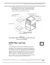
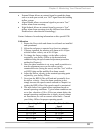
Setting the Inflow Face Velocity
with the Speed Control
Adjustment
1. Remove the front panel by loosening the (2) Phillips screws
on top that secure the front panel.
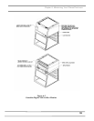
2. The speed control is located on the electrical subassembly
located behind the switched control panel and below the
front panel. See Figure 6-1.
3. Adjust the speed control with a small Phillips screwdriver
by turning the screw counterclockwise to increase blower
speed or clockwise to decrease the blower speed. The
speed control is very sensitive, so proceed with caution.
4. Measure the inflow velocity per the averaging technique
outlined in Chapter 3 and adjust the speed control slowly
for the desired speed. Allow the speed to stabilize and re-
measure the inflow velocity to confirm.
5. Replace the front panel and tighten the screws.
XPERT
FILTERED
BALANCE
SYSTEM