


Model TS420
Quick Start Guide
vii
3. Calibrate the Detector.
Activating the “CAL” switch will automatically disable the external alarm circuits by fixing the
analog output current to 3.75mA.
General Monitors recommends that the TS420 be calibrated within the first twenty-four (24)
hours after initial start-up, and that calibration be checked at least every ninety (90) days to
ensure the integrity of the system.
NOTE: A calibration check consists of applying a 20.9% V/V O
2
(“normal” ambient air) of full-
scale concentration of gas to the sensor and observing the reading on the display device being
used.
General Monitors is not implying that the customer should expect problems with sensor life or
stability. “Frequent” calibration checks merely ensure the integrity of the life protecting
equipment, and are recommended for problem environments (i.e. sensors accidentally being
painted over, etc, see Appendix 5.4).
A calibration schedule should be established and followed. A logbook should also be kept
showing calibration dates and dates of sensor replacement.
Calibration Procedure:
1. If it is suspected that the air is not at “normal” levels (20.9% O
2
), it will be necessary to
calibrate the sensor with clean air. The 20.9% O
2
gas cylinder (GMI P/N 1400262-11) can be
used. Apply the clean air source prior to entering calibration mode and allow the sensor to
stabilize for at least one (1) minute before proceeding.
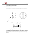
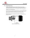
2. Place the magnet over the GMI Logo on the body of the unit and hold it there until the “CAL”
LCD indicator appears, then remove the magnet. The analog output current will drop to
3.75mA.
3. The “CAL” and “MODE” LCD indicator will flash, indicating that the unit is now calibrating.
4. After approximately 30 seconds, the display will change from a flashing “CAL” and “MODE”
LCD to a solid “MODE” LCD, indicating that the calibration is complete and the unit has re-
entered “OPERATE” mode. Remove any calibration gas.
6. The unit is now calibrated and the new values have been stored in the NOVRAM (non-
volatile memory).
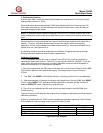
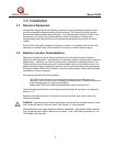
Figure Q-D shows a flow diagram of the codes that will appear in the display window during the
calibration procedure.
If there is a problem and the TS420 cannot complete the calibration sequence, a fault indicator
will be displayed, and the analog output current will drop to 3.5mA.
CALIBRATION INDICATOR
CAL MODE
Magnet Applied
❑ ■
Magnet Recognized
■ ❑
Cal Proceeding
✹ ✹
Figure Q-D Flow Diagram