


Model TS420
7
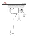
3.4 Wiring Connections
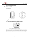
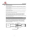
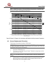
The two wires at the base of the TS420 provide a 4-20mA loop-powered output. The red wire
is the “loop +” lead and the white wire is the “loop -” lead (Figure 4). A third green/yellow wire is
provided for frame ground.
It is recommended that a two wire, shielded cable be used for making power and output signal
connections on the TS420.
Connect the green/yellow frame ground wire to the grounding terminal or lug inside the junction
box being used with the TS420.
Ensure the junction box frame is connected to frame ground or connected to the cable shield,
which is connected to frame ground at the controller.
Connect the red wire to the +24VDC terminal. Connect the white wire to the signal input
terminal on the readout/relay display module, FMD Field Mounted Display, S4100E smart
sensor, industrial analog to digital converter, computer-based monitor, PLC, DCS, etc.
Since the TS420 is designed to operate continuously, a power switch is not included, in order to
prevent accidental system shutdown.
NOTE - Power must remain disconnected until all wiring connections are made.
The absolute maximum distance between the TS420 and the power supply is 8000 feet (2438
meters). Depending on the application, general purpose or intrinsically safe, the cable length
will depend on the intrinsically safe barrier chosen and the cable used. See the Appendix,
Section 5.1.5, for the intrinsically safe system requirements. In addition, cable length
specifications can also be found in the Appendix, Section 5.1.3. In all cases, the cable run
should be as short as possible.
Figure 4 Wiring Diagram
LOOP - (WHITE)
CONTROL
ROOM
LOOP + (RED)
JUNCTION BOX
RED
WHITE
GRN/YEL
TS420