


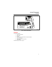

Infrared Thermometer
Typical Measurements
15
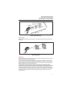
• If system pressure has been increased above design settings, this can result in symptom of trap
failure (stuck open). Check steam pressure.
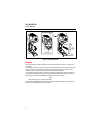
1. Press
D and then press A to select HI emissivity for black iron pipe and painted traps.
2. Press
C and then press A to select DIF.
3. Aim the Thermometer at the steam pipe.
4. Scan steam pipe upstream of trap.
5. Scan the steam trap. Scan downstream of trap on condensate return side.
6. Press
C and then press A and toggle to MIN, MAX, and DIF temperatures. Record your
readings.
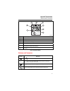
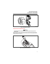
Measuring Grille, Register, or Diffuser Discharge Temperature
1. Press D and then press A to select HI emissivity.
2. Aim the Thermometer at the discharge air grille, register, or diffuser.
3. Measure discharge temperature.
4. Release the trigger to freeze the temperature reading for 7 seconds and record the temperature.
5. Grille, register, or diffuser temperature should be equivalent to discharge temperature at the air
handler.
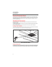
6. Drill a sample hole in supply duct at air handler.
7. Connect thermocouple probe to Thermometer.
8. Insert thermocouple probe, such as the 80PK-25 or 26, into the supply duct.
9. Read supply air temperature on the secondary display.
10. Compare supply duct temperature to discharge air temperature. They should be nearly equivalent. If
they are not, check for duct leakage or insulation problems.
11. Patch the sample hole.
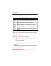
Verifying Thermostat/Room Sensor Accuracy
1. Insert the thermocouple probe into the Thermometer. Record ambient air temperature.
2. Press
D and then press A to select HI emissivity.
3. Press
C
and then press A to select DIF.
4. Aim the Thermometer at the wall thermostat.
5. Compare the wall temperature reading to thermostat cover temperature and thermocouple air
temperature reading.
6. Look for possible source of heat or heat sink that could be affecting thermostat accuracy.
7. The temperature of the thermostat cover and surrounding wall surfaces should be very nearly
equivalent (DIF reading should be close to 0).
Checking for Blockage in Air-To-Air Evaporators or Condensers
1. Remove panels to gain access to coil return bends or hairpins.
2. Press
D and then press A to select LO emissivity for copper tube.
3. Start the refrigeration system.
4. Aim the Thermometer at coil return bends/hairpins.
5. Start recording temperature.
6. Take temperature of each return bend/hairpin.
• All evaporator return bends/hairpins should be at or slightly above evaporator saturation
temperature from the pressure/temperature chart.