


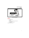

561 HVACPro
Users Manual
12
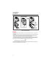
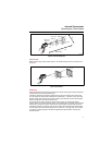
Testing Contactors (Starters)
1. Press D to select emissivity. Press A to select LO for bright contacts, or MED for darkened
contacts.
2. Press
Cand the press A to select MAX.
3. Measure line and load side of one pole without releasing trigger.
4. A temperature difference between the line and load sides of a pole indicate increased resistance of
one point and a contactor may be failing.
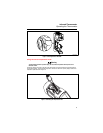
Testing Enclosed Relays
1. Press D and then press A to set emissivity to LO for uninsulated connectors or HI for plastic
encased relays or for bakelite enclosed relays or insulated connectors.
2. Press
C and then press A to select MAX.
3. Start the scan.
4. Measure the relay casing, looking for hot spots.
5. Measure electrical connections on relay terminals looking for hot spots.
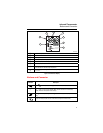
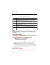
Testing Fuses and Buss Connections
1. Press D and then press A to set emissivity to HI for paper covered fuse body or insulated
connections.
2. Press
C and then press A to select MAX.
3. Scan the paper covered length of fuse.
4. Without releasing the trigger, scan each fuse. Unequal temperatures between fuses may indicate
voltage or amperage imbalance.
5. Press
D and then press A to select LO, for metal fuses end caps and uninsulated buss
connections.
6. Press
C and then press A to select MAX.
7. Scan each end cap on each fuse.
Note
Unequal temperatures or a high temperature indicates loose or corroded connection through
the fuse buss spring clip.
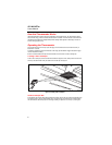
Testing Electrical Connections
1. Press D and then press A to select LO emissivity for uninsulated connectors or buss
connections or HI for insulated connections.
Note
Conductors are typically smaller than the Thermometer’s spot size. If the spot size is bigger
than the connector, the temperature reading is the average within the spot.
2. Scan the conductor, moving toward direction of electrical connector (quick connect, wire nut, buss
connection, or lug).