


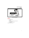

Infrared Thermometer
Typical Measurements
11
• The most likely conditions for condensation formation are low dry bulb temperature and high wet
bulb temperature (low temperature, high relative humidity).
• Use the Fluke 971 to measure the attic/crawlspace relative humidity and determine the dew point
temperature. This is the temperature at which condensation will form on the duct wrap.
• Use the thermocouple to measure the duct wrap surface temperature. The temperature must remain
above the attic or crawlspace dew point temperature at all times.
• In attics, the most likely time for dew point concerns is at night after the attic has cooled. Less heat
in the attic means less heat gain by the duct wrap, which will be closer to the dew point temperature.
• Crawlspaces are always cooler and problematic. Tight ductwork and liberal duct insulation is
essential. Sealing openings, insulating perimeter walls, laying a continuous vapor barrier, and adding
a low temperature, high capacity dehumidifier is often required to eliminate moisture and fungal
problems.
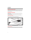
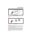
Testing Insulated Return Ducts
1. Connect a thermocouple probe.
2. Place the thermocouple probe in the return air stream at the return grille.
3. Read the return air temperature in the secondary temperature display.
4. Open a small test hole in the return duct at the air handler.
5. Place thermocouple probe into the return air stream at the air handler (For consistency, use the same
probe as in step 2. 80PK-25, 80PK26 probes, or similar, are recommended for use through duct test
holes.)
6. Read the return air temperature in the secondary display.
7. Seal the test hole when finished.
Note
Temperature differential should be negligible (less than 1 to 2 degrees). If the temperature
difference is too much, air leaks or insufficient duct insulation is indicated.
8. Seal duct connections at grilles, boxes, plenums, transitions, and take-offs.
9. Retest.
If the test does not show satisfactory improvement, then remove duct insulation, seal duct seams and
joints, re-wrap insulation, seal insulation facing at all seams to ensure continuous vapor barrier.
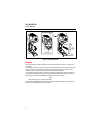
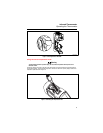
Scanning Walls for Air Leaks or Insulation Deficiencies
1. Turn off heating, cooling, and blower.
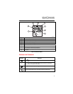
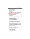
2. Press
D to select emissivity. Press A to select HI for painted surfaces or window surfaces.
3. Press
C and select MIN when opposite side of wall is at lower temperature and or select MAX
when opposite side of wall is at higher temperature.
4. Measure an interior partition wall surface temperature. Do not release the trigger. Record this
temperature as your baseline (or benchmark) for a “perfectly” insulated wall.
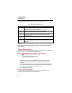
5. Face the wall to be scanned. Stand 2.4 m (8 ft) away to scan an 20.3 cm (8 in) spot on the wall.
6. Scan horizontal rows of wall from top to bottom, or horizontal rows of ceiling from wall to wall. Look
for greatest deviations from baseline temperature to identify problems. This completes the insulation
test scan.
Turn on the blower (no heat, no cooling) and retest. If test results with the blower on are different than
results with the blower off, this may indicate air leaks in conditioned envelope walls. The air leaks are
caused by duct leaks that create a pressure differential across the conditioned space envelope.