


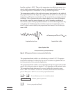
9 Digital Communication Interface
The dry-well calibrator is capable of communicating with and being controlled
by other equipment through the digital interface. Two types of digital interface
are available — the RS-232 serial interface and the IEEE-488 GPIB interface.
With a digital interface the instrument may be connected to a computer or other
equipment. This allows the user to set the set-point temperature, monitor the
temperature, and access any of the other controller functions, all using remote
communications equipment.
9.1 Serial Communications
The calibrator is installed with an RS-232 serial interface that allows serial
digital communications over fairly long distances. With the serial interface the
user may access any of the functions, parameters and settings discussed in Sec
-
tion 8 with the exception of the BAUD rate setting.
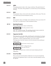
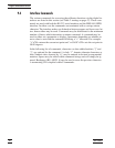
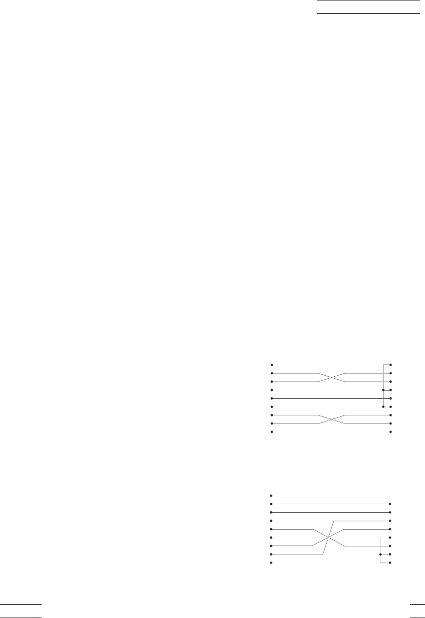
9.1.1 Wiring
The serial communications ca-
ble attaches to the calibrator
through the DB-9 connector at
the back of the instrument. Fig-
ure 9 shows the pin-out of this
connector and suggested cable
wiring. To eliminate noise, the
serial cable should be shielded
with low resistance between the
connector (DB9) and the shield.
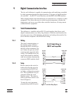
9.1.2 Setup
Before operation the serial in
-
terface must first be set up by
programming the BAUD rate
and other configuration parame
-
ters. These parameters are pro
-
grammed within the serial
interface menu. The serial in
-
terface parameters menu is out
-
lined in Figure 6.
To enter the serial parameter
programming mode first press
9105/9107 43
9 Digital Communication Interface
RS-232 Cable Wiring for
IBM PC and Compatibles
1NC
2 RxD
3 TxD
4NC
5 GND
6NC
7RTS
8 CTS
9NC
2 TxD
3 RxD
4RTS
5 CTS
6 DSR
7 GND
8 DCD
20 DTR
Instrument
Connector
(DB 9-Pin)
Computer (DTE)
Connector
(DB 25-Pin)
1NC
2 RxD
3 TxD
4NC
5 GND
6NC
7RTS
8 CTS
9NC
1 DCD
2 RxD
3 TxD
4 DTR
5 GND
6 DSR
7RTS
8 CTS
9NC
Instrument
Connector
(DB 9-Pin)
Computer (DTE)
Connector
(DB 9-Pin)
Figure 9 Serial Cable Wiring Diagram