


Quick Installation Guide
00825-0100-4801, Rev HA
February 2008
Rosemount 3051S
8
STEP 4 CONTINUED...
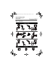
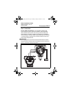
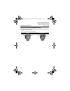
Remote Display Wiring and Power Up
The Remote Mount Display and Interface system consists of a local
transmitter and a remote mount LCD display assembly. The local
3051S transmitter assembly includes a Junction Box housing with a
three position terminal block integrally mounted to a SuperModule.
The remote mount LCD display assembly consists of a dual
compartment PlantWeb housing with a seven position terminal block.
See Figure 4 on page 9 for complete wiring instructions. The following
is a list of necessary information specific to the Remote Mount Display
system:
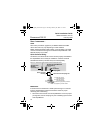
• Each terminal block is unique for the remote display system.
• A 316 SST housing adapter is permanently secured to the remote
mount LCD display PlantWeb housing providing an external
ground and a means for field mounting with the provided mounting
bracket.
• A cable is required for wiring between the transmitter and remote
mount LCD display. The cable length is limited to 100 ft.
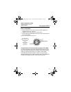
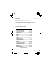
• 50 ft. (option M8) or 100 ft. (option M9) cable is provided for wiring
between the transmitter and remote mount LCD display. Option
M7 does not include cable; see recommended specifications
below:
Cable type: Recommend Belden 3084A DeviceNet cable or Belden
123084A Armored DeviceNet cable. Other comparable cable may be
used as long as it has independent dual twisted shielded pair wires
with an outer shield. The Power wires must be 22 AWG minimum and
the CAN communication wires must be 24 AWG minimum.
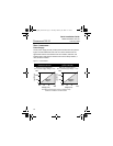
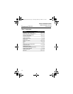
Cable length: Up to 100 feet depending upon cable capacitance.
Cable capacitance: The capacitance from the CAN communications
line to the CAN return line as wired must be less than 5000 picofarads
total. This allows up to 50 picofarads per foot for a 100 foot cable.
4801_QIG_RevHA.fm Page 8 Tuesday, February 26, 2008 12:17 PM