


Quick Installation Guide
00825-0100-4593, Rev BA
July 2009
Rosemount 1151
10
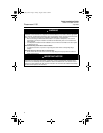
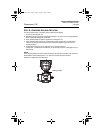
STEP 5: CALIBRATE THE TRANSMITTER
Verify Transmitter Configuration
NOTE:
A check (✓) indicates the basic configuration parameters. At minimum, these parameters
should be verified as part of the configuration and startup procedure.
Table 1. HART Communicator Fast Key Sequence
Function Fast Key Sequences
Analog Output 3
Analog Output Alarm 1, 4, 3, 3
Burst Mode Control 1, 4, 3, 4, 3
Burst Operation 1, 4, 3, 4, 4
Calibration 1, 2, 3
Characterize 1, 4, 1, 1, 2, 2
✓ Damping 1, 3, 6
Date 1, 3, 4, 1
Descriptor 1, 3, 4, 2
Digital-to-Analog Trim (4–20 mA Output) 1, 2, 3, 2, 1
Field Device Information 1, 4, 4, 1
Full Trim 1, 2, 3, 3
Keypad Input 1, 2, 3, 1, 1
Loop Test 1, 2, 2
Lower Range Value 4, 1
Lower Sensor Trim 1, 2, 3, 3, 2
Message 1, 3, 4, 3
Meter Type 1, 3, 4, 5
Number of Requested Preambles 1, 4, 3, 4, 2
Percent Range 1, 1, 2
Poll Address 1, 4, 3, 4, 1
Pressure 2
✓ Range Values 1, 3, 3
Rerange 1, 2, 3, 1
Scaled D/A Trim (4–20 mA Output) 1, 2, 3, 2, 2
Self-Test (Transmitter) 1, 2, 1, 1
Sensor Information 1, 4, 4, 2
Sensor Trim Points 1, 2, 3, 3, 4
Status 1, 2, 1, 2
✓ Tag 1, 3, 1
✓ Transfer Function (Setting Output Type) 1, 3, 5
Transmitter Security (Write Protect) 1, 3, 4, 4
Trim Analog Output 1, 2, 3, 2
✓ Units (Process Variable) 1, 3, 2
Upper Range Value 5, 2
Upper Sensor Trim 1, 2, 3, 3, 3
Zero Trim 1, 2, 3, 3, 1
4593_Rev_BA.fm Page 10 Friday, August 7, 2009 3:38 PM