5 - 4 Troubleshooting Guide
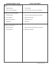
Excessive pressure drop across dryer.
1. Badly broken, dusted or fouled desiccant.
2. Inlet flow rate (SCFM) is exceeding the
dryer’s design flow rate as specified on the
Dryer Specification Label located on the in-
side cover of the dryer system control enclo-
sure.
3. Desiccant retaining screens are clogged or
fouled.
4. Inlet and/or outlet pressure gauges are out of
calibration, or damaged.
Chamber depressurization (prior to each regen-
eration cycle) is excessively loud.
1. The purge exhaust flow restrictor is dam-
aged, or not fully seated.
1. Shutdown and Depressurize Dryer. Inspect desiccant
through fill ports and replace if badly broken, dusted or fouled.
Note: If the “normally white” desiccant is fouled or discolored,
inspect prefilter cartridges and drain valve or trap.
2. Reduce the inlet flow rate as necessary to meet the dryer’s de-
sign flow rate.
3. Shutdown and Depressurize Dryer. Drain desiccant from
chamber. Inspect retaining screens through fill and drain ports
and clean if fouling is noted. Investigate and remedy source of
fouling.
CAUTION: Desiccant may be reinstalled if it is not fouled or
badly broken.
4. Shutdown and Depressurize Dryer. Replace damaged, faulty
or out-of-calibration gauges.
1. Shutdown and Depressurize Dryer. Proceed as follows:
a) For Model LS1250 only.
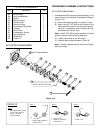
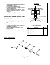
1. Provide adequate support for muffler and flow
restrictor assembly. Remove flow restrictor assembly
from lower flange by equally loosening flange bolts. En-
sure that the method of support is prepared to ac-
cept the Muffler’s full weight when the last bolt is
removed (see following CAUTION).
CAUTION: Exercise caution when lowering flow
restrictor and muffler to prevent damaging control tub-
ing, and the Purge Pressure Indicator.
2 Remove, clean and inspect the “spring and orifice-type”
flow restrictor. Install a new flow restrictor if damage is
noted.
Important: When installing Flow Restrictor, its springs
MUST be fully seated in the spring receptacle. This
MUST be accomplished for proper operation.
3 Reinstall muffler and flow restrictor in the reverse order
of removal.
PROBLEM/POSSIBLE CAUSE CHECKS AND REMEDY


