


4 - 14 Maintenance and Repair
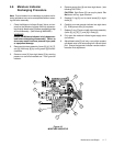
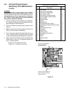
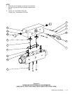
4.10 2" Purge Exhaust
Switching Valve Maintenance
(Model LS1250 only)
WARNING!
Ensure that the Dryer is de-energized, valve isolated,
and fully depressurized before attempting to remove
or disassemble any Dryer component or subassem-
bly. Failure to do so may result in serious personal
injury and/or equipment damage.
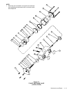
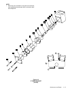
Note: Removal of valve body [16] from the dryer manifold
is not required unless replacement of square O-rings [17]
or valve body is necessary.
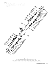
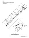
Note: Exploded view illustrates one-half of switching
valve only. Disassembly of opposite half (not shown ex-
ploded), is identical.
1. Clean and inspect all valve hardware upon disassem-
bly. Replace all software and any hardware which
appears damaged or abnormally worn.
2. Clean and inspect valve seat located inside the valve
body [16]. As previously noted, this can be accom-
plished without removing the valve body [16] from the
dryer manifold.
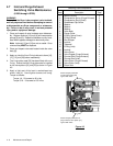
3. Apply an ultra-thin film of O-ring lubricant to items [3],
[5], [8], [11], and [17] before reassembly. Do not ap-
ply lubricant to the valve seat seal [13].
4. The U-cup piston seal [5] has been fitted with a cut O-
ring. Ensure that the U-cup piston seal is installed on
the valve piston [4] as shown. The open side of the
U-cup piston seal [5] must face the valve cover [2]
upon reassembly.
5. Apply a light coat of lubricant to the sockethead cap
screws, items (1) and (18). Hand tighten screws until
snug. Torque to 245 in-lbs.
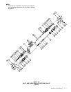
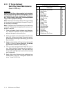
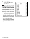
2" Switching Valve Components
Item Description Total
1 Sockethead Cap Screw 8
2 Valve Cover 2
3 O-Ring 4
4 Valve Piston 2
5 Piston Seal 2
6 Bonnet Cylinder 2
7 Valve Bonnet 2
8 O-Ring 2
9 Rod Scraper 2
10 Poppet Shaft 2
11 O-Ring 2
12 Seal Retainer 2
13 Valve Seat Seal 2
14 Retaining Disc 2
15 Seal Nut 2
16 Valve Body 1
17 Square O-Ring 2
18 Sockethead Cap Screw 4