


16
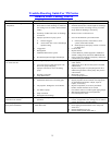
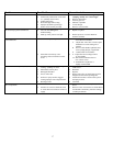
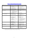
Trouble-Shooting Guide For TM Series
Induced Draft Cooling Towers
Problem Possible Causes Corrective Actions
Increase in the leaving water
temperature
1. Excess water flow; over pumping.
2. Recirculation of hot discharge air, back into
the cooling tower air intakes. Obstructed air
intakes
3. Proximity of other heat source or discharge
of moist air.
4. Improper operation of spray system.
A. Orifices clogged.
B. Actual water flow is lower than design
sprinkler rating.
5. Clogged fill.
6. Damaged fill.
7. Additional heat load on system.
8. Wet-bulb temperature higher than design.
1. Adjust to the design flow.
2. Eliminate obstructions which impede air discharge.
For proper location of cooling tower(s), see Delta
dwgs. Baffle air discharge, if necessary.
3. Remove source or relocate tower.
4. See water distribution system instructions.
A. Flush spray nozzles, clean orifices, clean
system, install outlet strainer.
B. Install properly rated spray nozzles or increase
to design flow.
5. Clean the fill.
6. Replace the fill.
7. Contact Delta for possible upgrade or addition of
another cooling tower selected for additional load.
8. None required if condition is temporary. Otherwise
consult Factory for upgrade.
Drop in the water flow rate.
Low water flow rate
1. Blockage of spray Nozzle orifices.
2. Low water level in sump causing air to be
drawn into pump and piping.
3. Improper selection of water circulating
pump.
4. Blockage of strainers.
5. Pump malfunction.
1. Flush spray nozzle. Clean whole system. Install
outlet strainer.
2. Adjust float valves. Be sure the system is flooded
and balanced.
3. Replace with proper size pump designed for flow
and head requirements. Check pump “Net positive
suction head.”
4. Backwash or clean.
5. Consult pump specialist.
Noise and vibration 1. Loose bolts.
2. Mechanical interference of rotating parts.
3. Fan propeller damaged or out of balance.
4. Air intake at pump.
5. Pump cavitation.
6. Damaged motor bearings.
1. Recheck and tighten all bolts to specified torque.
2. Inspect propeller for free rotation. Check propeller
for mechanical interference. Adjust, repair or
replace, as necessary.
3. Replace components, as necessary and check
balance. Install vibration cut-out switch.
4. Check basin water level and irregular piping design.
5. Match pump NPSH with system hydraulics.
6. Check and replace motor.
Sudden or short term irregularities of
cold water level in basin
1. Peculiarities of specific system and its
operation.
1. Inspect system and review operation procedures.
Correct, as applicable valve settings, loss of water in
system, fill system to flooded capacity.
Excessively high water level in sump on
gravity drain installation
1. Gravity flow restrictions due to insufficient
head differential.
1.
A. Outlet piping should terminate below sump tank
water level.
B. Increase discharge pipe size.
C. Increase head by mean other than A.