26
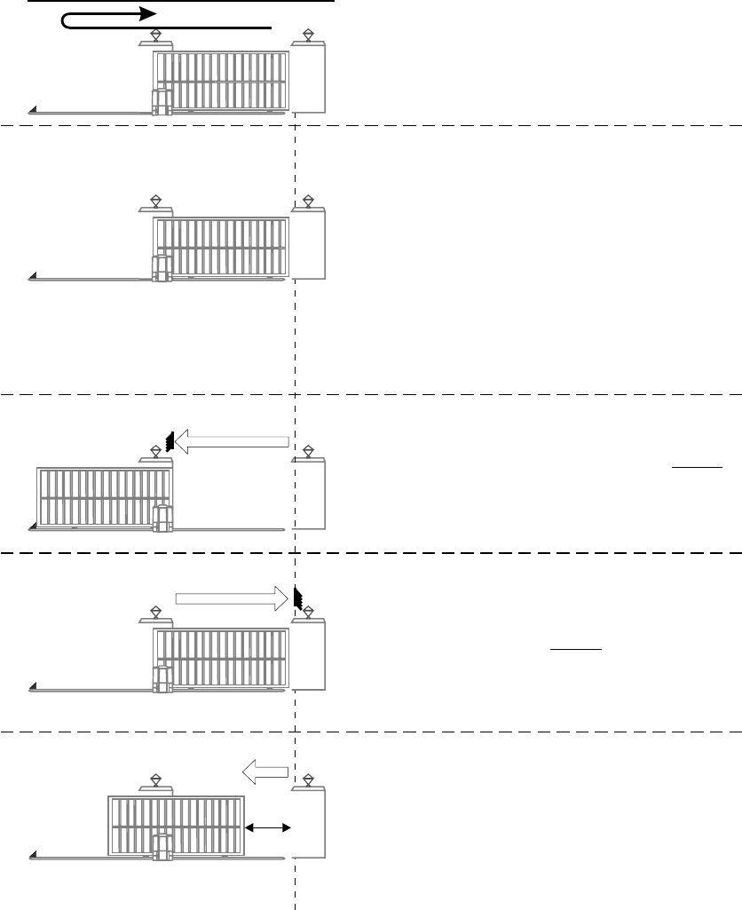
- Start with gate fully closed.
- Push gate open (origin marker must have
moved well past origin switch).
- Push gate closed again.
STEP 2 - ENSURE PCB IS IN PROGRAMME
MODE (refer procedure page 21)
STEP 4
- Push gate to fully “OPEN” position and do not
allow gate to reverse.
- Press TEST pushbutton until STATUS LED
comes ON and release.
STEP 1 ALIGN ORIGIN SWITCH
STEP 5
- Push gate to fully “CLOSED” position hard
up against endstop and do not allow gate
to reverse.
- Press TEST pushbutton until STATUS LED
comes ON and release.
STEP 3 - SET LIMITS
- Press TEST pushbutton until LED L1 flashes
once and release.
- L1 will continue to flash once and L2 will
go out.
- Press TEST pushbutton until STATUS LED
comes ON and release (check that L1, L2 &
STATUS are OFF)
STEP 6
- Push gate to “PEDESTRIAN” open position.
- Press TEST pushbutton until STATUS LED
comes ON and release. If STATUS LED
does not come ON, increase pedestrian
opening until it does.
A5 MOTOR MANUAL SET-UP
“PED”


