


Using Limit Level Indicator
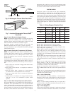
The final setting of the bypass for best performance has always
been something of a black art. The 3-Zone System has a new
feature to simplify this adjustment. While the system is operating,
these limit level numbers, if greater than zero, are flashed on the
status LED.
Once the proper LAT limit choice is made based on equipment
maximum rise, the limit level indicator assists in setting the bypass
pressure adjustment. See System Setup for details.
Installer Test Mode
Dipswitch 4 selects a special Installer Test Mode, designed to
assist the installer (or service person) to commission the system. It
verifies damper movement in proper zone and that the heating and
cooling equipment operates properly at each stage. When this
mode is selected, by moving dipswitch 4 to ON, the following
sequence will be executed once:
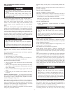
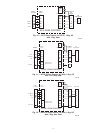
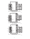
Step 1 — Two minutes, one flash of status LED. The blower is
energized with G, damper 1 opens, and other dampers are closed.
Step 2 — Two minutes, two flashes of LED: With the blower on,
damper 1 closes and damper 2 opens.
Step 3 — Two minutes, three flashes of LED: With the blower
ON, damper 3 opens and damper 2 closes.
Step 4 — Two minutes, four flashes of LED: All dampers open,
first stage of heat turns on. For HP control only, this is followed by
the second stage of heat (HP plus aux heat, hi HP, or hi furnace)
for two more minutes. For HP control with two stage compressor,
the third stage of heat (hi HP plus aux heat) comes on for a third
2 minute period.
Step 5 — Two minutes, five flashes of LED: All dampers are open
and first stage of cooling turns on for 2 minutes. For HP board
only, second stage of cooling comes on for an additional 2
minutes.
At the end of Step 5, the control returns to normal operation. To
restart the test sequence, the switch must be moved to OFF and
then back to ON.
If zoning is disabled (Switch 5 = ON), the procedure above will be
followed, except all the dampers will remain open throughout the
sequence.
SYSTEM SETUP
Thermostats
Read the thermostat Installation Instructions and be sure to
complete the required setup of these devices before using them to
bring on the equipment. If the thermostats have a ″zoning″
selection, be sure to turn it on. This will eliminate the timers within
the thermostat and allow the 3-Zone control’s timers to do their
job.
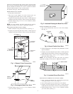
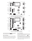
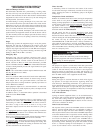
There are 8 dipswitch settings on the AC zone control and an
additional 4 on the HP board. Below is a table summarizing their
function. Below the table is a more detailed description of what
each does and how to set it properly for your application.
Dipswitches
Dipswitch 1- This determines whether or not a minimum time
must pass before the control is allowed to transition between
heating and cooling or vice versa. If it is set to ON, there is no time
requirement. Default is OFF.
Dipswitch 2 - This switch, together with dipswitch 3, determines
the changeover time, effective if switch 1 is OFF. ON sets 30
minutes. OFF sets 20 minutes. Default is OFF.
Dipswitch 3 - This is a multiplier, modifying the time set on switch
2. ON multiplies the set time by 0.5. OFF multiplies the set time
by 1.0. Default is OFF.
Dipswitch 4 - This selects the Installer Test Mode, used to check
system operation. Details are provided in section Installer Test.
ON selects Installer Test. OFF selects normal operation. Default is
OFF.
Dipswitch 5 - Enables and disables zoning. ON disables zoning,
with all dampers open and zone 1 thermostat controlling. OFF
selects normal zoning operation. Default is OFF.
Dipswitch 6 - Selects G ON or OFF with W. Selecting ON causes
G to be energized whenever W is energized. Selecting OFF does
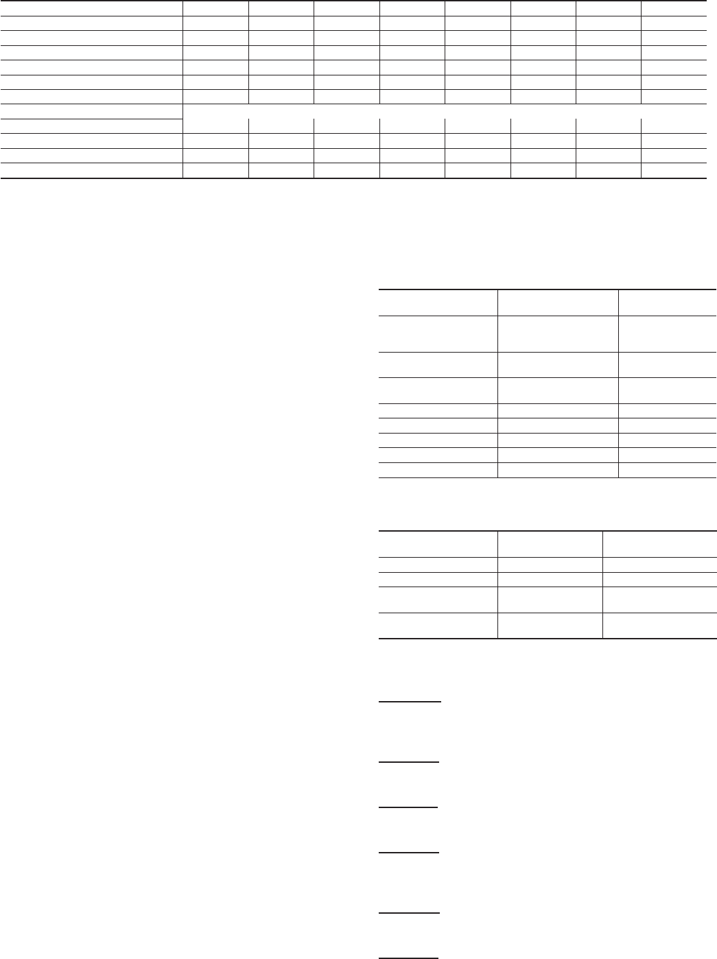
Table 2—Limit Temperature Levels and Actions
LIMIT LEVEL 01234567
Cooling Limit (40 deg) above 47 46 45 44 43 42 41 40
HP limit (115 deg) below 107 108 109 110 111 112 113 115
Heat Limit (130 deg) below 119 121 122 124 125 127 128 130
Heat Limit (145 deg) below 131 133 135 137 139 141 143 145
Heat Limit (160 deg) below 143 145 148 150 153 155 158 160
Heat Limit (175 deg) below 155 158 161 164 166 169 172 175
LIMIT ACTIONS
″Closed″ Damper Positions 02468101214
Allowed stages (1 stg) 11111110
Allowed Stages (2 stg) 22211110
Allowed stages (3 stg) 33322110
Table 3—Dipswitch Settings
DIPSWITCH 1 POSITION
ACTION
(OFF)
ACTION
(ON)
1
Auto changeover Timer
Active
Defeat
Auto Changeover
Timer
2
Auto Changeover 20 Min-
utes
Auto Changeover
30 Minutes
3
Auto Changeover Timer X
1
Auto Changeover
Timer X .5
4 Normal Operation Installer Test
5 Zoning Enabled Zoning Disabled
6 Fan With W Disabled Fan With W Enabled
7 LAT Setting LAT Setting
8 LAT Setting LAT Setting
Table 4—Dipswitch Settings
for HP Control Only
DIPSWITCH 2 POSITION
ACTION
(OFF)
ACTION
(ON)
9 HP Operation AC Operation
10 HP Thermostat AC Thermostat
11
LAT and HPT
Safeties Enabled
LAT and HPT
Safeties Disabled
12
Reversing Valve Ener-
gized in Cooling (O)
Reversing Valve
Energized in Heating (B)
7