


Connect the equipment R to both Rz and either Rh or Rc. A jumper
will be needed. Rc and Rh are internally connected but may be
separated by breaking a twist-off (see step 4 below).
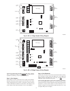
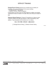
Step 3—Wire Dampers
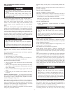
Each damper has three connections: Close, Open, and Common.
Find the connection points along the lower left side of the 3-Zone
Control. Suggested colors are Close = red; Open = green; Common
= white. Field label and make the connections at the dampers and
at the 3-Zone Control. Be careful not to cross zone numbers.
Step 4—Wire Remainder
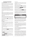
Connect the LAT sensor to the LAT and LATC terminals. Polarity
does not matter. If used, connect the HPT sensor to the HPT and
HPTC terminals. If the HPT sensor is not used, you must leave the
10K ohm resistor connected in its place.
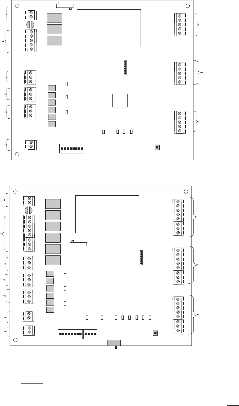
If the cooling and heating systems have separate transformers,
twist off the Rc/Rh jumper using a pair of long nosed pliers. Then
connect the R of the cooling transformer to Rc, the R of the heating
transformer to Rh and the common of both transformers to C.
Connect a jumper wire between Rz and Rc. Rc powers G, Y, and
O outputs. Rh powers W outputs.
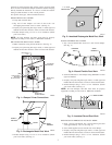
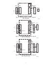
Fig. 8—AC or 1-Stage System Wiring Diagram
A04192
Rh
Rc
Y1
W1
G
R
C
Y1
W1
G
R
C
Y1
W1
G
R
C
Y1
W1
G
CLS_1
COM_1
OPN_1
CLS _2
COM_2
OPN _2
CLS _3
COM_3
OPN _3
C
Rz
LATC
LAT
ON
1 2 3 4 5 6 7
Relay
Relay
Relay
Fuse
Tri ac
Tri ac
Tri ac
Tri ac
Tri ac
Tri ac
Power Supply
Micro
WY1 G
Damper 1
Damper 2
Damper 3
Compressor
Timer Override
Status
Rc/Rh
Twist Off
Zone
Zone
Zone
Dipswitches 1- 8
To 24VAC
Power
To Equipment
To Zone 1
Damper
To Zone 2
Damper
To Zone 3
Damper
To LAT
Sensor
To Zone
Thermostat
To Zone
Thermostat
To Zone
Thermostat
Programming
Connector
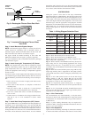
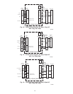
Fig. 9—HP or 2-Stage System Wiring Diagram
A04191
Rh
Rc
Y1
W1
G
Y2
W2
O
R
C
Y1
W1
G
Y2
W2
O
R
C
Y1
W1
G
Y2
W2
O
R
C
Y1
W1
G
Y2
W2
O
CLS_1
COM_1
OPN_1
CLS 2
COM_2
OPN 2
CLS 3
COM_3
OPN 3
C
R
HPT
HP
LATC
LAT
ON
1 2 3 4 5 6 7
1 2 3
ON
Relay
Relay
Relay
Relay
Relay
Relay
Fuse
Triac
Triac
Triac
Triac
Triac
Triac
Power Supply
Micro
WY1 G WY2 O
Damper 1
Damper 2
Damper 3
Compressor
Timer Override
E-Heat
Status
E-Heat
Rc/R
Twist Off
Zone
Zone
Zone
To Zone 1
Thermostat
To Zone 2
Thermostat
To Zone 3
Thermostat
To 24VAC
Power
To
Equipment
To Zone 1
Damper
To Zone 2
Damper
To Zone 3
Damper
To HPT
Sensor
To LAT
Sensor
Dipswitches 1 - 12
Connector
Programming
5