


Step 5—Install Barometric Bypass Damper
NOTE: The barometric bypass damper is a critical part of Carrier
3-Zone System for controlling noise at minimum airflow. A
barometric bypass should be installed unless the duct work and
indoor unit have been sized for use without a bypass.
The bypass should be installed according to local codes and
SMACNA standards. Be sure bypass is properly supported.
For proper installation, refer to Installation Instructions packaged
with barometric bypass.
Step 6—Install Leaving Air Temperature (LAT) Sensor
NOTE: The supplied LAT sensor must be installed for normal
operation. Heat pump systems may use an optional HPT (heat
pump temperature) sensor for added protection. These sensors
protect the equipment when leaving air temperatures approach
excessive levels.
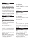
Locate LAT sensor in main supply trunk after heating and cooling
coil and before bypass damper and first branch. The LAT sensor is
radiant shielded to prevent heat from affecting correct air tempera-
ture.
1. Drill a 1/4-in. hole at location in supply trunk where sensor
will be installed.
2. Insert sensor in hole and use as a template to mark the 2
mounting holes.
3. Drill two 1/16-in. holes to accept No. 6 screws through
pre-drilled holes in duct temperature sensor back plate.
4. Use 2 No. 6 sheet metal screws to mount duct temperature
sensor to unit.
5. Connect sensor to 2-conductor wire using provided wire nuts.
(See Fig. 9, 10, or 11 for connection to Carrier 3-Zone
System.)
Step 7—Install Heat Pump Temperature (HPT) Sensor
The optional HPT sensor is recommended in all heat pump/fan coil
installations. If an optional HPT sensor is not used, the 10K ohm
resistor attached to the two HPT terminals on the board must be
left in place. The HPT sensor measures the temperature of the air
leaving the indoor coil. The sensor is to be installed downstream of
the indoor coil but before the electric heaters. It can be installed
through the wall of the fan coil or may be located entirely inside
the fan coil near the blower inlet. Anchor firmly in place with cable
ties so that it cannot interfere with the blower wheel.
SYSTEM WIRING
Wiring the system is best done in four steps. Thermostats,
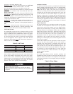
Equipment, Dampers, and Remainder. The descriptions below and
Table 1 will help you choose the correct wiring diagram for your
system. Table 1 also shows the proper setting of dipswitches 9 and
10 for each diagram. Based on the equipment, 3-zone control, and
thermostat type, select the appropriate wiring diagram. Terminal
designations on all the thermostats are those of Carrier thermostats.
Other brands may vary somewhat. Wiring diagrams and 3-Zone
Control board layouts are located at the end of this Installation
Instruction.
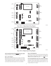
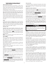
Fig. 8 - Shows the board layout for the AC Control.
Fig. 9 - Shows the board layout for the HP/2S Control.
Fig. 10 - Shows the 3-Zone AC Control wiring. It supports only 1
stage cooling and 1 stage heating.
Fig. 11 - Shows that the 3-Zone HP/2S Control may be used in 1
stage cooling and 1 or 2 stage heating applications. For 2 stage
heating, the stat may be a 2 stage heat AC stat or a HP stat
converted to AC. (Carrier HP stats can be field converted to 2 stage
heat AC stats.)
Fig. 12 - Shows the conventional HP system, using a HP stat. Only
single stage auxiliary heat is supported for heat pump systems.
Using the HP stat allows control of emergency heat directly from
the stat.
Fig. 13 - Is also a HP system, but uses an AC stat with 2 stage
heating instead of a HP stat. (Carrier HP stats can be field
converted to 2 stage heat AC stats.) Here, emergency heat can only
be selected by a switch on the 3-Zone Control.
Fig. 14 - Is a 2 speed AC system and may have 1 or 2 stages of
heat. An HP/2S Control and a 2S stat set for AC operation must be
used.
Fig. 15 - Is for a 2 speed HP. It requires an HP/2S Control and a
2S stat set for HP operation. Only single stage auxiliary heat is
supported for heat pump systems.
Step 1—Wire Thermostats
All zone thermostats are wired identically, so only the Zone 1
thermostat is shown on the wiring diagrams. For physical location
of connections on 3-Zone Control refer to Fig. 8 (AC Control) or
9 (HP Control).
Battery or power stealing thermostats may not require the C
connection. Refer to thermostat Installation Instructions. Be care-
ful not to cross zone numbers.
Step 2—Wire Equipment
Again, from the selected Fig. 10 through 13, make each connection
as shown at the indoor and outdoor units and the 3-zone Control.
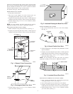
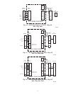
Fig. 6—Rectangular Fibrous Glass Duct Work
A92480
ZONE
DAMPER
2″ TO 3″
FIBROUS
GLASS
DUCTWORK
FIELD
SUPPLIED
SCREWS
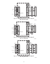
Fig. 7—Insulated Rectangular Fibrous Glass
Duct Work
A95134
1 / ″ TO 2″
INSULATION
1
2
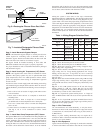
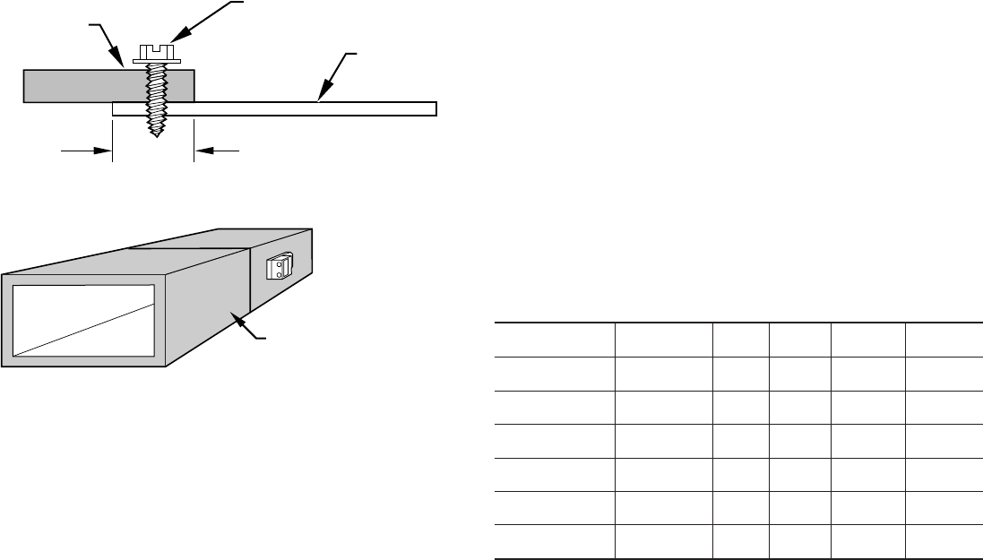
Table 1—Wiring Diagram Selection Chart
WIRING DIAGRAM EQUIPMENT
3-ZONE
TYPE
STAT
TYPE
SWITCH 9 SWITCH 10
Fig. 10
1-spd. AC,
1-Stg. heat
AC AC not present not present
Fig. 11
1-spd. AC,
1 or 2-stg. heat
HP/2S AC ON ON
Fig. 12
1-spd. HP,
1-stg. aux heat
HP/2S HP OFF OFF
Fig. 13
1-spd. HP,
1-stg. aux heat
HP/2S AC (2 ht) OFF ON
Fig. 14
2-spd. AC,
1 or 2-stg. heat
HP/2S 2S (AC) ON ON
Fig. 15
2-spd. HP,
1-stg. aux heat
HP/2S 2S (HP) OFF OFF
4