


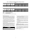
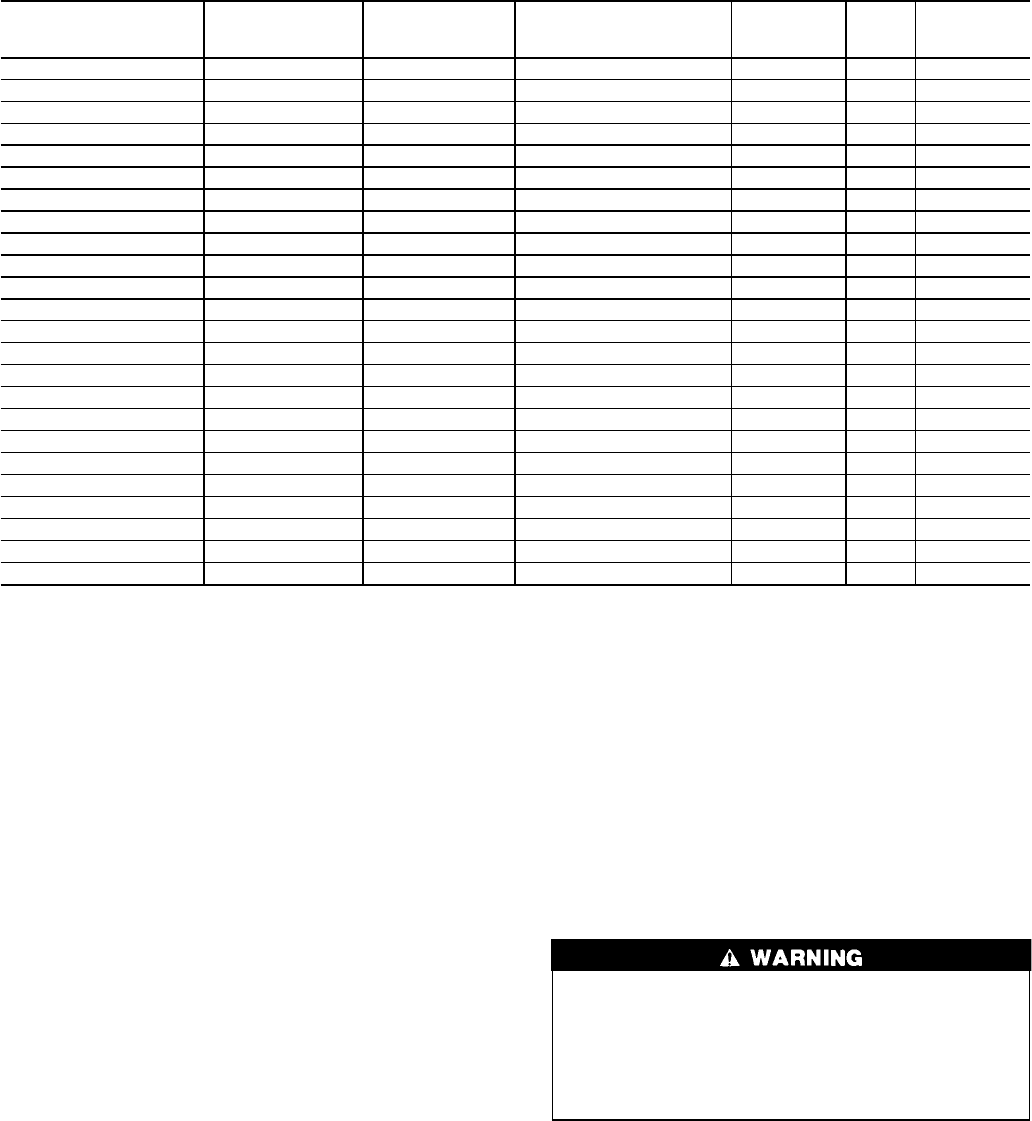
Table 1 — Positive Pressure System Assembly Numbers
POSITIVE PRESSURE
SYSTEM ASSEMBLY
NUMBER
PUMPOUT UNIT
ASSEMBLY NO.
REFRIGERANT
COMPRESSOR MOTOR
(V-Ph-Hz)
MAXIMUM
RLA
LRA
STORAGE
TANK
19XB04280205 19EA42-748 R-22 208-3-60 13.2 63.5 28 cu ft
19XB04280206 19EA44-748 R-22 230-3-60 11.5 57.5 28 cu ft
19XB04280207 19EA46-748 R-22 400/460-3-50/60 5.8 28.8 28 cu ft
19XB04280208 19EA47-748 R-22 575-3-60 4.6 23.0 28 cu ft
19XB04280213 19EA48-748 R-134a 208-3-60 13.2 63.5 28 cu ft
19XB04280214 19EA49-748 R-134a 230-3-60 11.5 57.5 28 cu ft
19XB04280215 19EA51-748 R-134a 400/460-3-50/60 5.8 28.8 28 cu ft
19XB04280216 19EA52-748 R-134a 575-3-60 4.6 23.0 28 cu ft
19XB04280601 19EA42-748 R-22 208-3-60 13.2 63.5 None
19XB04280602 19EA44-748 R-22 230-3-60 11.5 57.5 None
19XB04280603 19EA46-748 R-22 400/460-3-50/60 5.8 28.8 None
19XB04280604 19EA47-748 R-22 575-3-60 4.6 23.0 None
19XB04280605 19EA48-658 R-134a 208-3-60 13.2 63.5 None
19XB04280606 19EA49-658 R-134a 230-3-60 11.5 57.5 None
19XB04280607 19EA51-658 R-134a 400/460-3-50/60 5.8 28.8 None
19XB04280608 19EA52-658 R-134a 575-3-60 4.6 23.0 None
19XB04520205 19EA42-748 R-22 208-3-60 13.2 63.5 52 cu ft
19XB04520206 19EA44-748 R-22 230-3-60 11.5 57.5 52 cu ft
19XB04520207 19EA46-748 R-22 400/460-3-50/60 5.8 28.8 52 cu ft
19XB04520208 19EA47-748 R-22 575-3-60 4.6 23.0 52 cu ft
19XB04520213 19EA48-748 R-134a 208-3-60 13.2 63.5 52 cu ft
19XB04520214 19EA49-748 R-134a 230-3-60 11.5 57.5 52 cu ft
19XB04520215 19EA51-748 R-134a 400/460-3-50/60 5.8 28.8 52 cu ft
19XB04520216 19EA52-748 R-134a 575-3-60 4.6 23.0 52 cu ft
LEGEND
LRA — Locked Rotor Amps
RLA — Rated Load Amps
NOTES:
1. All storage vessels are 300 psig (2068 kPa) designs per the ASME
(American Society of Mechanical Engineers) Boiler Pressure
Vessel Code, Section VIII Division 1.
2. All unitsabove are shipped with a 15 psig (103kPa) nitrogen charge.
3. Nominal horsepower for all pumpout units is 3.0.
Mount the Pumpout Unit — The pumpout unit, if pur-
chased separately, may be mounted directly on the chiller or
it may be floor mounted.
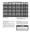
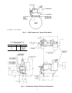
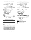
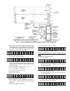
MOUNTING ON THE CHILLER — See instructions pro-
vided with the chiller for mounting the pumpout unit.Atypi-
cal chiller mount is shown in Fig. 2.
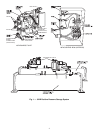
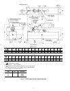
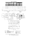
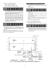
FLOOR MOUNTING — Select a ventilated and accessible
area, free of traffic or other hazards. Remove and discard the
4 angle supports at the base of the pumpout unit and bolt the
unit to the floor through the 4
7
⁄
16
in. holes at the base of the
pumpout unit. Special isolation is unnecessary. Contact sur-
face and dimensions for the pumpout unit are given in
Fig. 3.
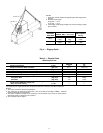
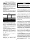
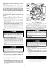
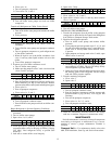
Rig the Storage Tank — The complete 19XB system
can be rigged as a single assembly. See the rigging instruc-
tions on the label attached to the assembly. Also refer to the
rigging guide (Fig. 4), physical data in Tables 2 and 3, and
contact surface and dimensions for the complete system in
Fig. 5. Lift the assembly only from the 4 points indicated in
the rigging guide. Each rigging cable must be capable of
supporting the entire weight of the assembly.
Lifting the assembly from points other than those speci-
fied may result in serious damage to the assembly and
personal injury. Rigging equipment and procedures must
be adequate for assembly. See Tables 2 and 3 for weights.
NOTE: These weights are broken down into pumpout
unit and storage tank weights. For the complete assem-
bly weight, add all components together.
3