


NOTE: During this operation, maintain water circulation
through the chiller cooler and condenser vessels to prevent
tube freeze-up.
DISTILLING THE REFRIGERANT — Refrigerant vapor
is transferred from the chiller cooler vessel or pumpout stor-
age tank through the pumpout condenser, condensed to a liq-
uid, and pumped to the chiller condenser vessel. During this
operation, water circulation must be maintained in the pump-
out condenser. Refrigerant impurities left in the chiller cooler
vessel or storage tank are then drained off. This operation
can take from 4 to 14 hours, depending on the type and amount
of refrigerant being distilled.
The Pumpout and Refrigerant Transfer Procedures sec-
tion gives step-by-step instructions on performing these
operations.
Pumpout and Refrigerant Transfer Procedures
—
Three possibilities are available:
1. If there are no isolation valves on the chiller, a complete
pumpout system with a pumpout storage tank and pump-
out unit is needed.
2. Whether or not isolation valves are available on the chiller,
the refrigerant can be pumped to and isolated in a pump-
out storage tank by using the pumpout unit.
3. If isolation valves are available on the chiller, the refrig-
erant can be pumped to either the cooler vessel or the
condenser vessel using the pumpout unit.
The following procedures describe how to transfer refrig-
erant from one vessel to another and how to evacuate the
chiller.
Do not mix refrigerants from chillers that use different
compressor oils. Compressor damage can result. For ex-
ample, the compressor oil in a 23XL chiller that uses
HCFC-22 refrigerant can cause severe lubrication prob-
lems in a 19XL chiller that uses HCFC-22 refrigerant.
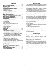
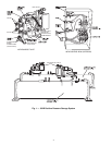
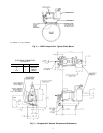
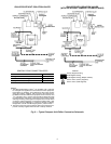
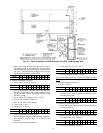
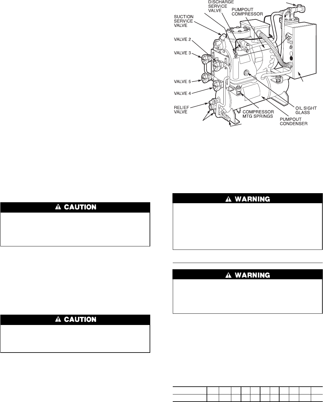
OPERATING THE PUMPOUT UNIT
1. Be sure that the suction and the discharge service valves
on the pumpout compressor (Fig. 9) are open (back-
seated) during operation. Rotate the valve stem fully coun-
terclockwise to open. Frontseating the valve closes the
refrigerant line and opens the gage port to compressor
pressure.
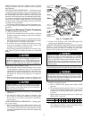
2. Make sure that the pumpout compressor holddown bolts
(Fig. 2) have been loosened to allow free spring travel.
Transfer, addition, or removal of refrigerant in spring-
isolated chillers may place severe stress on external pip-
ing if springs on the chiller have not been blocked in
both up and down directions.
3. Open the refrigerant inlet valve (Fig. 9) on the pumpout
compressor.
4. Oil should be visible in the pumpout compressor sight
glass under all operating conditions and during shut-
down. If oil is low, add oil as described in the Mainte-
nance section.
TO READ REFRIGERANT PRESSURES — During pump-
out or leak testing:
1. Refer to the display on the chiller control center to de-
termine refrigerant-side pressures and low (soft) vacuum.
Use a quality vacuum indicator or manometer to measure
evacuation and dehydration and to ensure the desired range
and accuracy.
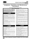
2. Attach a 30 in.-0-400 psi (101-0-2760 kPa) gage to the
storage tank to determine its pressure.
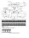
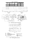
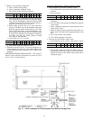
POSITIVE PRESSURE CHILLERS WITH STORAGE
TANKS — In the Valve/Condition tables that accompany
these instructions, the letter ЉCЉ indicates a closed valve.
Figures 9 and 10 show the locations of the valves.
Always run chiller cooler and condenser water pumps
and always charge or transfer refrigerant as a gas when
chiller vessel pressure is less than 60 psig (414 kPa)
[30 psig (207 kPa)]. Below these pressures, liquid re-
frigerant flashes into gas, resulting in extremely low tem-
peratures in the cooler/condenser tubes and possibly causing
tube freeze-up.
Transfer Refrigerant from Pumpout Storage Tank to Chiller:
During transfer of refrigerant into and out of the 19XB
storage tank, carefully monitor the storage tank level gage.
Do not fill the tank more than 90% of capacity to allow
for refrigerant expansion. Overfilling may result in dam-
age to the tank and personal injury.
1. Equalize refrigerant pressure.
a. Turn on chiller water pumps and monitor chiller
pressures.
b. Close pumpout and storage tank valves 2, 4, 5, 8, and
10, and close refrigerant charging valve 7; open chiller
isolation valve 11 and any other chiller isolation valves,
if present.
c. Open pumpout and storage tank valves 3 and 6; open
chiller valves 1a and 1b.
VALVE 1a1b23456781011
CONDITION C C C C C C
d. Gradually crack open valve 5 to increase chiller pres-
sure to 60 psig (414 kPa), [ 30 psig (207 kPa)]. Slowly
feed refrigerant to prevent freeze-up.
OIL RETURN
LINE
CONNECTION
CONDENSER
WATER
CONNECTIONS
REFRIGERANT
INLET VALVE
VENT VALVE 8
PUMPOUT
CONTROL BOX
(WIRING BY
CONTRACTOR)
Fig. 9 — Pumpout Unit
12