


PUMPOUT COMPRESSOR OIL CHARGE — Use oil con-
forming to Carrier specifications for reciprocating compres-
sor use. Oil requirements are listed in Table 6.
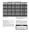
Table 6 — Pumpout Compressor Oil Requirements
REFRIGERANT
ISO
VISCOSITY
CARRIER
SPECIFICATION
NO.
CARRIER
PART NO.
R-22 86 PP49-7 PP23BZ101
R-134a 68 PP47-31 PP23BZ103
The total oil charge, 4.5 pints (2.6 L), consists of 3.5 pints
(2.0 L) for the compressor and one additional pint (0.6 L)
for the oil separator.
Oil should be visible in one of the pumpout compressor
sight glasses both during operation and at shutdown. Always
check the oil level before operating the pumpout compres-
sor. Before adding or changing oil, relieve the refrigerant
pressure as follows:
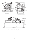
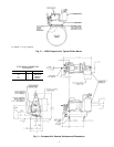
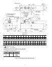
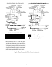
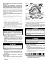
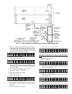
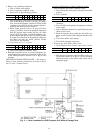
1. Attach a pressure gage to the gage port of either pumpout
compressor service valve (Fig. 10).
2. Close the suction service valve and open the discharge
line to the pumpout storage tank or the chiller.
3. Operate the compressor until the crankcase pressure drops
to 2 psig (13 kPa).
4. Stop the pumpout compressor and isolate the pumpout
system by closing the discharge service valve.
5. Slowly remove the oil return line connection (Fig. 9). Add
oil as required.
6. Replace the connections and reopen the pumpout com-
pressor service valves.
Storage Tank — To prevent moisture and contami-
nants from entering the storage tank, maintain positive pres-
sure in the tank when not transferring refrigerant. Leak test
the storage tank according to your normal vessel leak test
procedures and schedule.
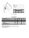
Ordering Replacement Parts — The following in-
formation must accompany an order for Carrier-specified parts:
• machine model number and serial number
• name, quantity, and part number of the part required
• delivery address and method of shipment
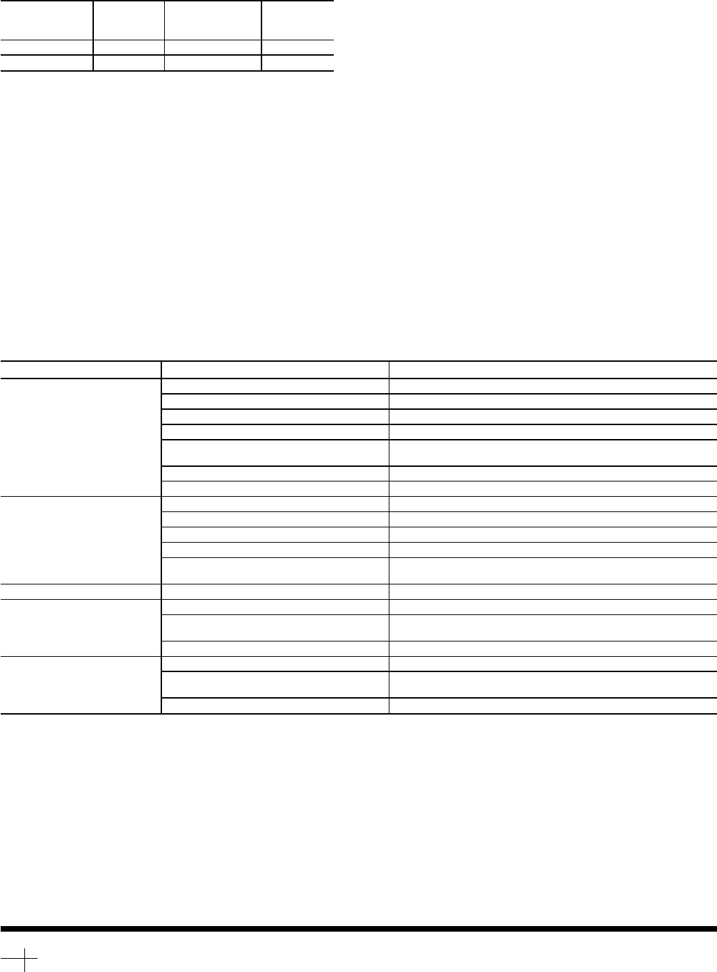
TROUBLESHOOTING
Information on troubleshooting for the PPS is included in
Table 7.
Table7—Troubleshooting
SYMPTOM PROBABLE CAUSE REMEDY
Compressor does not run Main power line open Replace fuse or reset circuit breaker.
Loose terminal connection Check connections.
Improperly wired controls Check wiring and rewire.
Low line voltage Check line voltage; determine location of voltage drop.
Compressor motor defective Check motor winding for open or short. Replace compressor if
necessary.
Seized compressor Replace compressor.
High level gage alarm Check refrigerant level and remove excess.
Compressor cycles on
high-pressure control
High-pressure control erratic in action Check capillary tube for pinches. Set control as required..
Discharge valve partially closed. Open valve.
Air in system Purge system.
Condenser scaled. Clean condenser.
Condenser water pump or fans not operat-
ing.
Start pump or fans.
Unit operates too long Isolation valves partially open Close valves.
System Noises Piping vibrations Support piping as required. Check for loose pipe connectors.
Compressor noisy Check valve plates for valve noise. Replace compressor (worn
bearings). Check for loose compressor holddown bolts.
Insufficient compressor oil Add oil.
Compressor Loses Oil Leak in system Locate and repair leak.
Plugged or stuck compressor oil return
check valve
Repair or replace valve.
Dirty accumulator Clean accumulator.
Copyright 1996 Carrier Corporation
Manufacturer reserves the right to discontinue, or change at any time, specifications or designs without notice and without incurring obligations.
Book 2
Tab 5a
PC 211 Catalog No. 531-927 Printed in U.S.A. Form 19XB-1SI Pg 16 6-96 Replaces: New