


e. Open valve 5 fully after the chiller pressure rises above
the freezing point of the refrigerant. Let the storage
tank and chiller pressure equalize. Open refrigerant charg-
ing valve 7 and storage tank charging valve 10 to let
liquid refrigerant drain into the chiller.
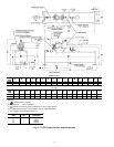
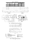
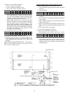
VALVE 1a1b23456781011
CONDITION C C C
2. Transfer remaining refrigerant.
a. Close valve 5 and open valve 4.
VALVE 1a1b23456781011
CONDITION C C C
b. Turn off the pumpout condenser water, and turn on the
pumpout compressor to push liquid refrigerant out of
the storage tank. Monitor the storage tank level until
the tank is empty.
c. Close refrigerant charging valves 7 and 10.
d. Turn off the pumpout compressor.
e. Turn off the chiller water pumps.
f. Close valves 3 and 4.
g. Open valves 2 and 5.
VALVE 1a1b234567 81011
CONDITION C C C C C
h. Turn on pumpout condenser water.
i. Run the pumpout compressor until the storage tank pres-
sure reaches 5 psig (34 kPa), 18 in. Hg (41 kPa
absolute).
j. Turn off the pumpout compressor.
k. Close valves 1a, 1b, 2, 5, and 6.
VALVE 1a1b23456781011
CONDITION C C CCCCCCC C
l. Turn off pumpout condenser water.
Transfer the Refrigerant from Chiller to Pumpout Storage
Tank.
1. Equalize refrigerant pressure.
a. Valve positions:
VALVE 1a1b23456781011
CONDITION C C C C C C
b. Slowly open valve 5 and refrigerant charging valves 7
and 10 to allow liquid refrigerant to drain by gravity
into the storage tank.
VALVE 1a1b23456781011
CONDITION C C C
2. Transfer the remaining liquid.
a. Turn off pumpout condenser water. Place valves in the
following positions:
VALVE 1a1b23456781011
CONDITION C C C
b. Run the pumpout compressor for approximately 30 min-
utes, then close valve 7 and 10.
VALVE 1a1b234567 81011
CONDITION C C C C C
c. Turn off the pumpout compressor.
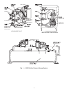
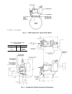
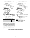
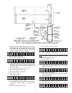
Fig. 10 — Valve Locations for 19XB Pumpout Unit With 19XB Storage Tank
13