Page 7
Floor Level and Inner Roll Stop Adjustments
Achieving proper floor level positioning of the plat-
form and inner roll stop requires a combination of
Floor Level switch adjustment and inner roll stop
adjustment. Both are factory set but must be in-
spected during installation procedures (will vary per
vehicle application).
Ensure the lift is positioned and secured as speci-
fied on Quick Reference Installation Sheet (sup-
plied with lift) panels 1 and 2. Adjust the Floor
Level switch first (detailed below). Then, adjust
the inner roll stop as detailed in Inner Roll Stop
Adjustment Instructions (adjust only if necessary).
The inner roll stop must rest properly on the vehicle
floor for wheelchair entry and exit.
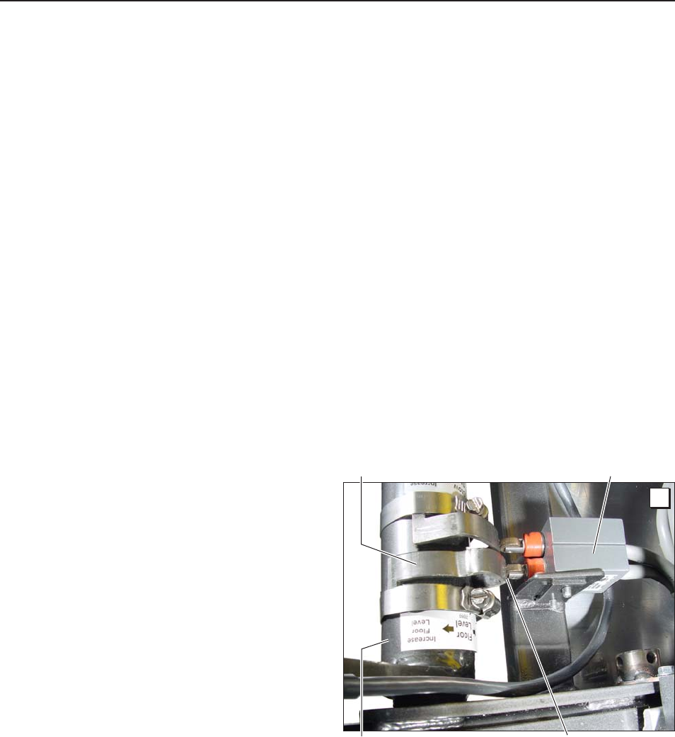
The Floor Level switch stops upward travel of the
platform during the Up function (activated by the
torque tube-mounted Floor Level cam).
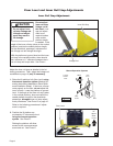
Position the bottom of the lift platform 1 1/2" above
floor level (threshold mat) using the manual op-
eration system. Do not operate the lift with the
electric pump during adjustment procedures.
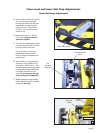
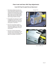
Loosen the clamp securing the torque tube-mount-
ed Floor Level cam. Rotate the cam until the Floor
Level switch is activated (cam depresses switch).
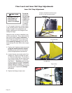
Note: Check the floor level position of the platform
and the inner roll stop after powering the pump.
Hydraulic pressure may affect platform height
slightly. Fine tuning adjustment (tweaking) of the
Floor Level switch may be required.
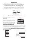
Floor Level Switch Adjustment
Adjust the Floor Level switch first!
(before adjusting the inner roll stop)!
Floor Level Switch
Floor Level Cam
Torque Tube
A
Cam depressing switch.
Note: Lift model NUVL855RM24 depicted in
adjustment photos. Adjustment procedures are
applicable for lift model NUVL855RM24.


