


Page 8
O
P
E
N
C
L
O
S
E
VALVE
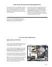
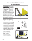
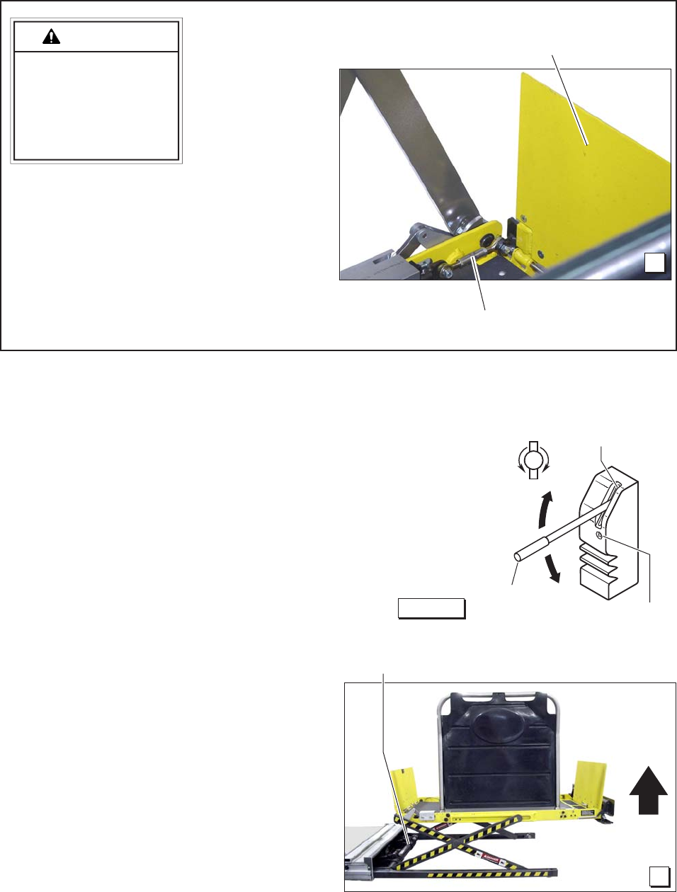
2. Position the lift platform ap-
proximately 12" above stow level
using the manual operation
system. See Photo C.
Raising the platform will allow
access to the cam securement
screw and nut. See Photo E.
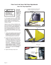
Inner Roll Stop Adjustment
CAUTION
Do not adjust inner
roll stop linkage rod.
Linkage rod adjust-
ment may result in
lift damage.
Do not adjust
inner roll stop
linkage rod at
this time! Link-
age rod adjust-
ment is not
required unless
extra usable
platform length
is needed. If the
angle of the inner roll stop (when in the vertical
position) restricts the usable platform length
for the wheelchair passenger, adjustment of
the linkage rod will change the angle.
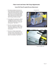
With the platform at ground level and the inner
roll stop in the vertical position, there should
be a minimum of 1" clearance between the in-
ner roll stop and torque tube. See Photo I.
Inner Roll Stop
Linkage Rod
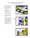
1. Raise the lift platform fully (floor level) using
the manual operation system (Manual Op-
erating Instructions detailed on Quick Refer-
ence Installation Sheet). If the inner roll stop
rests properly on the floor, do not adjust the
inner roll stop. Lower the platform to ground
level. If the angle of the inner roll stop (when
in the vertical position), does not restrict the
usable platform length for the wheelchair
passenger, disregard inner roll stop adjust-
ment procedures. See Photo G on page 10.
Refer to the following procedures if adjust-
ment is required.
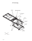
Stow Level
Platform
12
"
above
Stow
Level
B
C
Hand
Pump
Valve
Pump
Handle
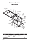
Figure A
Manual Operation Systems
T-Handle
Release
Cable
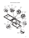
Floor Level and Inner Roll Stop Adjustments
Adjust the inner roll stop as detailed in the fol-
lowing procedures. Then, adjust the linkage rod
as detailed on page 10 (only if necessary).