


Page 5
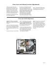
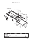
Adjustment Procedures
Lift Out Switch: The Lift Out Switch stops inward
travel of the carriage/platform during Stow function
(activated by the housing-mounted Lift Out Cam).
Move cam in to increase inward travel. Move cam
out to decrease inward travel.
Full Out Switch: The Full Out Switch stops out-
ward travel of the carriage/platform during Deploy
(Up/Down) functions (activated by the housing-
mounted Full Out Cam). Move cam in to decrease
outward travel. Move cam out to increase outward
travel. Carriage rollers must be inside housing a
minimum 1/2". The platform will not raise or lower
until this switch is activated.
Floor Level Switch: See page 6 for procedures.
Stow Switch: The Stow Switch controls the height
of the carriage/platform before it moves inward dur-
ing the Stow function (activated by the torque tube-
mounted Stow Cam). Rotate the cam in to decrease
platform height. Rotate the cam out to increase plat-
form height. Adjust cam so lifting arms are aligned.
View the platform position in the housing.
Barrier Down Switch: This platform-mounted
switch prohibits the platform from raising unless the
outer barrier is in the full up position. The Up func-
tion is prohibited if the outer barrier detent pin is not
fully engaged also.
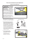
Drive Chain Adjustment
In event the drive chain sags 1/2" or more, adjust
tension as detailed. Tighten to eliminate visible sag
but do not overtighten.
1. Remove bottom pan.
2. Pull the manual release cable and lock.
3. Remove adjustment bolt (tensioner) access
cover.
4. Loosen inside jam nut. Secure tensioner and
tighten outside jam nut. Tighten to eliminate vis-
ible chain sag but do not overtighten.
5. Lock jam nuts together making sure the ten-
sioner roller is horizontal. Release and push the
manual cable in fully. Ensure platform is locked
by moving the platform in and out until chain
release assembly engages chain.
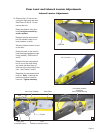
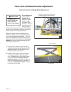
Carriage Ride Height Adjustment
The carriage horizontal arms move (roll) in and out
of the housing tracks on roller bearings. Follow-
ing installation or extensive lift operation, clearance
between horizontal arms and tracks may diminish.
The eccentric shaft mounting plate allows height
adjustment.
Remove eccentric plate mounting screw. Using
screwdriver or small rod, rotate the shaft clockwise to
increase carriage height. Rotate the shaft coun-
terclockwise to decrease carriage height. Reinstall
mounting screw in nearest retainer hole. Adjust
left and right side eccentric shafts (screw positions
may vary from side to side). Adjust height such that
horizontal arms do not contact top or bottom of tracks
(align center).
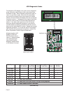
Calibration Procedures
Platform Sense Calibration
1. Place 20 lbs. in the center of the platform.
2. Press UP button on the hand-held pendant to raise
the platform a minimum of 3" above stow level.
3. Press and hold 50# CAL button on control board.
While pressing the 50# CAL button, press and
hold the STOW button on the hand-held pendant.
The platform will lower to stow level, raise slightly,
lower to stow level, and begin inward travel.
Release the 50# CAL button when the platform
begins moving inward. The platform sensing is
now calibrated.
4. After calibration, the LCD screen should read “PF
OCCUPIED” when 50 lbs., or more, are present
on the platform. If 50 lbs. does not activate the
“platform occupied” signal readout, recalibrate with
less weight to lower the “occupied” setting or more
weight to increase the “occupied” setting.
Ground Sense Calibration
1. Press hand-held pendant DOWN switch to lower
platform fully to ground level.
2. While continuing to press the pendant DOWN
switch, press and then release the control board
O_BAR/GROUND LVL button.
3. Release the pendant DOWN switch. Ground
Level sensing is now calibrated.
4. After calibration, the outboard roll stop should
not unfold (down) until the platform is fully on the
ground.
Outer Barrier Occupied Calibration
1. Press hand-held pendant DOWN switch to lower
platform fully to ground level.
2. Once outer barrier is fully unfolded (ramp position),
release the pendant DOWN switch.
3. Press and hold the control board O_BAR/
GROUND LVL button. While holding O_BAR/
GROUND LVL button, press hand-held pendant
UP switch to raise the outer barrier. Be sure to
release O_BAR/GROUND LVL button when outer
barrier reaches approximately half full up (vertical)
position.
4. After calibration, the LCD screen should read
“OUT-BAR OCCUPIED” whenever there is weight
present on the outer barrier.
Adjustments and Calibration