


9
Test Overview/Procedures
To make PARD measurements, the electronic load
used should operate in CR mode for constant volt-
age and constant current power supplies. The load
should also have lower PARD than the power sup-
ply being tested. This is especially important when
measuring the PARD of linear power supplies, since
they typically have excellent PARD specifications.
A regulated AC source should be applied to the
input of the power supply under test. PARD meas-
urements are made at the lowest and highest speci-
fied values of AC input to the power supply, and at
the lowest and highest specified source frequencies.
Proper connections between the instruments and
power supply under test are essential when making
these measurements. Since PARD consists of low
level, broadband signals, major test set concerns
are ground loops, proper shielding, and impedance
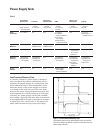
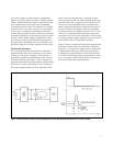
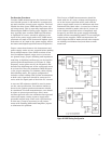
matching. A digitizing oscilloscope can be used for
peak-to-peak measurements (see Figure 8). High
frequency noise spikes need to be measured, and
therefore the digitizing rate of the oscilloscope must
be at least five times the maximum PARD frequen-
cy for proper sampling. To eliminate cable ringing
and standing waves, the typical configuration
includes coaxial cabling with 50 Ohm terminations
at both ends. Capacitors should be connected in
series with the signal path to block the DC current.
A true rms RF voltmeter should be used to meas-
ure the rms specification. Precautions similar to
those for the peak-to-peak measurements should
be considered. For both measurements, care should
be taken to prevent ground loops. Since most
oscilloscopes and true rms voltmeters have ground
referenced inputs, testing a power supply with
grounded outputs may create such a ground loop.
In this case, it may be necessary to use instru-
ments with floating (differential amplifier) inputs
to eliminate this problem.
The first set of PARD measurements should be
made with the AC source voltage and frequency
set at the lowest specified values, and with the
power supply under test at its minimum and then
maximum rated load value. A second set of meas-
urements should be made with the AC source set
at the highest specified values of amplitude and
frequency, and with the power supply minimally
loaded and then maximally loaded. To test multiple
output power supplies, PARD measurements for
each output should be made with all other outputs
set initially to minimum load, and then to maxi-
mum load.
Figure 8. PARD Testing Configuration