


12
An observation of any DC power supply data sheet
from a power supply manufacturer reveals a number
of design specifications that must be verified and
tested. These tests often differ in technique and in
the test equipment that is used to measure the var-
ious parameters. The common aspect of all of these
tests is that a method of controlled loading of the
power supply outputs is required, which is most
easily done with an electronic load. The list below
contains a brief description of some of these tests.
Drift
This test involves the measurement of the periodic
and random deviation of a power supply’s output
current or voltage (typically over 8 hours), typically
covering a bandwidth from DC to 20 Hz. The elec-
tronic load used for this test should be able to oper-
ate in CC or CV mode.
Test Equipment:
• Computer (for long-term testing)
• Electronic Load
• True rms Voltmeter
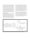
Source Effect (Line Regulation)
A measurement of the change in the output voltage
or current due to a change in the source voltage
magnitude. The output of interest is measured
after it settles within the regulation specifications.
The electronic load used for this test should be
able to operate in CC or CV mode.
Test Equipment:
• Electronic Load
• Regulated AC Source
• Digital Multimeter
• Precision Current Shunt
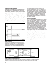
Short Circuit Output Current
This test measures the steady-state current of the
power supply under test after the output terminals
have been shorted. The short circuit can be provided
by an electronic load operating in CR mode.
Test Equipment:
• Electronic Load
• Digital Multimeter
• Precision Current Shunt
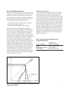
Overvoltage Shutdown
Typically, a power supply is expected to shut down
if its output voltage exceeds the maximum input
voltage of its intended load, the maximum operating
voltage of the power supply, or a variably set volt-
age limit. The overvoltage protection test demon-
strates the ability of the power supply under test
to correctly respond to any of those conditions. An
electronic load in CC mode can be used to test the
output voltage response.
Test Equipment:
• Electronic Load
• Digital Multimeter
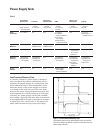
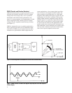
Programming Response Time
This test measures the maximum time required
for the programmed output voltage or current of
a power supply to change from a specified initial
value to a value within a specified tolerance band
of a newly programmed value, following the onset
of a step change in an analog programming signal,
or the gating of a digital signal. An electronic load
in CC, CR, or CV could be used in this test.
Test Equipment:
• Computer
• Electronic Load
• Digital Multimeter
• Precision Current Shunt
Other Power Supply Tests