


10
Efficiency
The efficiency of a power supply is simply the
ratio of its total output power to its total input
power. To obtain the true input power (rms voltage
x in-phase rms current) of a typical AC-to-DC
converting power supply, commercially available
wattmeters or AC sources can be used to measure
the necessary parameters. The instrument used
to measure the input current and voltage must be
capable of sampling the input signals at a rate
fast enough to produce accurate measurements.
This test serves as a good indication of the overall
correct operation of the power supply under test.
If the measured efficiency is outside the specified
range for the topology of the power supply, it is
probable that a design flaw or a manufacturing
problem exists that should be addressed.
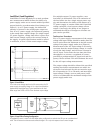
Test Overview/Procedures
The efficiency and power factor of the power supply
under test should be measured under steady-state
operation after the unit has been allowed to warm
up. The electronic load can be operated in CC mode
(for CV power supplies) and CV mode for (CC power
supplies). At least two load settings should be used,
one of them being the maximum rated load for the
power supply under test (see Figure 9 for test con-
figuration). Some power supplies vary substantially
in efficiency and power factor as a function of load-
ing. In this case, the load should be varied through
enough settings so that curves can be plotted from
the data to provide the best representation of the
test results.
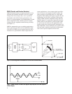
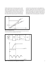
Start-Up
The start-up delay of a power supply is the amount
of time between the application of AC input and
the time at which the outputs are within their reg-
ulation specification. For switching power supplies
or power supplies with current limiting, this time
period is essential for proper sequencing of the out-
put voltage at turn-on. In switching power supply
designs, undesirable events can occur at turn-on,
causing current spikes which can destroy the switch-
ing transistors. The problem occurs when the feed-
back loop tries to compensate for the low output
voltage that it sees when the AC input is initially
applied to the power supply. This problem is usually
solved by adding “soft-start” circuitry to limit the
time the switching transistors are turned on during
the start-up sequence. This will limit the current
flow through them until the power supply has
reached stable operation.
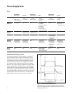
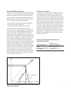
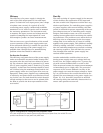
Another undesirable condition that can occur
during power supply start-up is voltage latch-up.
In this case, the output voltage of a CV power sup-
ply with current foldback fails to reach its full
value at turn-on because the output current attempts
to immediately go to a high value. The protective
response of the current foldback circuitry of the
power supply can cause the output voltage to “latch-
up” at a point where the current that must be dis-
sipated can cause damage to the power supply (see
Figure 10). It is, therefore, beneficial to measure
the start-up delay time and fully characterize it to
ensure safe operation at turn-on.
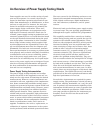
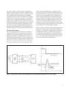
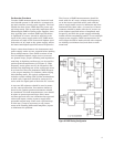
Figure 9. Configuration for Testing Efficiency and Power Factor
In this test configuration for measuring power supply efficiency and power factor, the variable AC source
provides measurements for input power and power factor.