


5
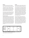
For a step change in load current, a marginally
stable CV power supply will have a ringing voltage
output. This defeats the purpose of the power sup-
ply’s regulation circuitry and can be damaging
to voltage-sensitive loads. An example of a voltage-
sensitive load is the logic circuitry in a computer.
In this case, a computer manufacturer that pur-
chases power supplies from an external source may
consider verifying the load transient recovery spec-
ification of the power supply subassembly. This
test can also reveal critical manufacturing flaws
that can cause instability, such as a defective out-
put filter capacitor or loose capacitor connections.
Test Overview/Procedures
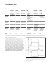
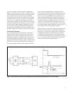
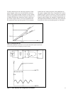
CV Load Transient Recovery Time is a dynamic
measurement of the time required for the output
voltage of a CV power supply to settle within a
predefined settling band following a load current
induced transient (see Figure 1). The response is
typically measured in microseconds or milliseconds,
and varies in value depending on the topology of
the power supply under test. The electronic load
used in this test should have a risetime at least
five times faster than the power supply under test,
and should be able to operate in CC mode (or CR
mode) up to the maximum current rating of the
power supply. Measuring the load transient recov-
ery time requires the load to have the capability
to pulse between two different values in CC or CR
mode. For continuous load transient testing, the
repetition rate of the pulses should be slow enough
so that the power supply feedback loop can recover
and stabilize after each applied transient.
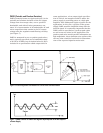
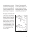
Figure 2 shows a typical test system for making load
transient recovery time measurements. Measure-
ment of V
out
of the power supply can be made with
a digitizing oscilloscope as the load input pulses
are applied. Synchronization of the measurement
is crucial in obtaining proper measurements. There-
fore, a common trigger should start the electronic
load and oscilloscope measurements.
Figure 2. Load Transient Recovery Test Configuration and V
OUT
Measurement Results for a CV Power Supply