


22
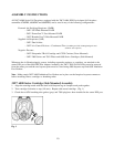
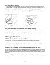
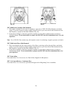
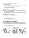
3M™ 6897 Head Harness Replacement
The 6897 head harness assembly consists of the head harness and buckles for the 3M 6000 series full
facepiece. To replace the head harness assembly:
1. Remove existing harness by pulling attachment buttons out of holes in faceseal tabs.
2. Attach new harness by pressing attachment buttons into holes in faceseal tabs with twisting motion. Be
certain buttons are fully seated. Head harness should be assembled with 2 short straps to top of
respirator and 3M and 6897 marking on harness facing away from respirator (Fig. 19).
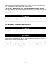
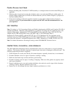
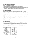
3M™ 6898 Lens Assembly
The 6898 lens assembly consists of a hard-coated polycarbonate lens with installed bayonet attachment
inhalation port fittings, inhalation valves, and inhalation port filter/cartridge gaskets. The 6898 lens is
replaceable by following these steps:
1. Remove nose cup assembly and center adapter assembly as described in previous DIN port adapter and
nose cup replacement sections.
2. Remove the (2) Phillips screws from the lens/faceseal frame. Pull the frame top and frame bottom away
from faceseal.
3. Remove faceseal from lens.
4. Place new lens and faceseal together aligning marks at top and bottom. Position top and bottom frame,
again aligning marks top and bottom (Fig. 20). Install and securely tighten screws. Make certain
alignment marks are properly aligned top and bottom with all components.
5. Install center adapter assembly.
6. Replace nose cup assembly.
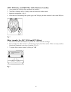
3M™ 6899 Frame Kit
The 6899 frame kit includes a frame top, frame bottom, (2) Phillips head screws and (2) hex head nuts. The
frame kit secures and seals the 3M 6000 series full facepiece faceseal to the 3M 6898 lens assembly.
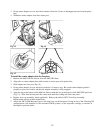
1. After assembling the faceseal onto the lens, matching top and bottom alignment marks, position top
frame, over lens and faceseal, aligning center vertical marks, then press in place.
2. Position bottom frame, aligning center vertical mark, and press in place (Fig. 20).
3. Insert and tighten Phillips head screws. Make certain parts are properly aligned and sealed together.
Fig. 19 Fig. 20