05/02 AWB2725-1452GB
Counter module
33
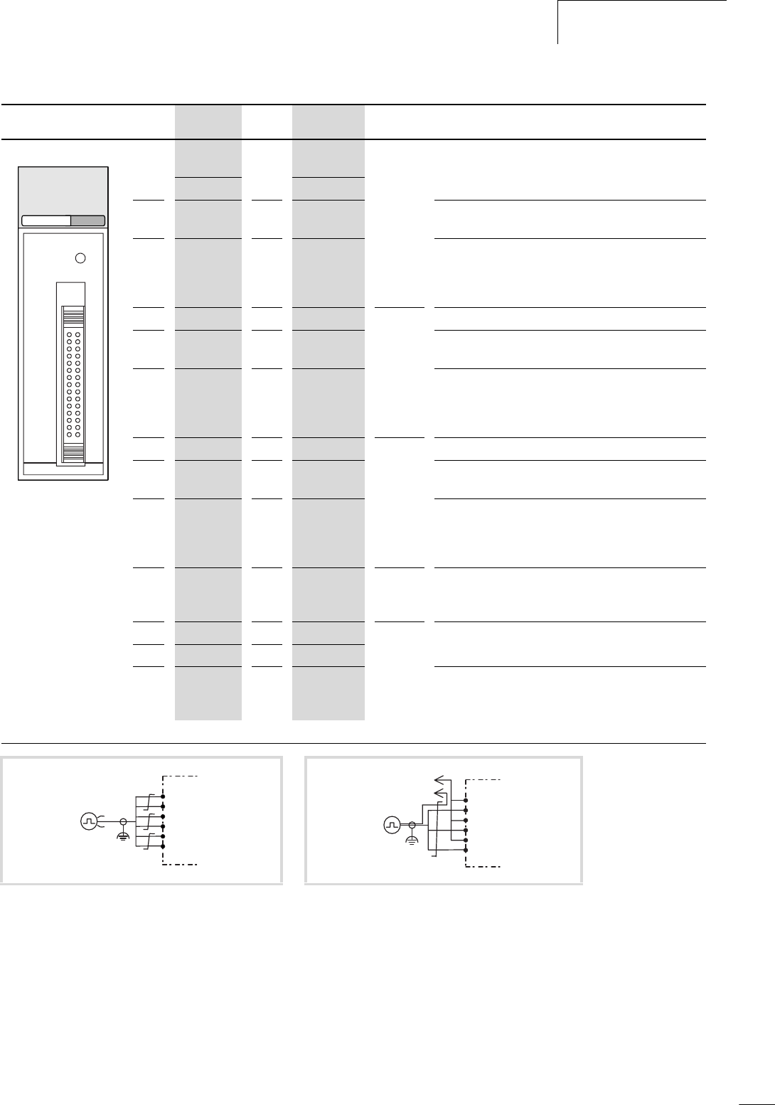
Terminal assignment No. CH2 No. CH1 Meaning of the signal
XIOC-2CNT XIOC-2CNT/
XIOC-1CNT
16 V
IN
A1V
IN
A Phase A If voltage input is used, connect to 12 to 24 V DC supply.
17 A (+) 2 A (+) If the differential input is used: connect to the positive
polarity.
18 A (–) 3 A (–) If the voltage input is used, connect to the open-
collector signal.
If the differential input is used, connect to the negative
polarity.
19
V
IN
B4V
IN
B Phase B If voltage input is used, connect to 12 to 24 V DC supply.
20
B (+) 5 B (+) If the differential input is used: connect to the positive
polarity.
21 B (–) 6 B (–) If the voltage input is used, connect to the open-
collector signal.
If the differential input is used, connect to the negative
polarity.
22
V
IN
M7V
IN
M Marker If voltage input is used, connect to 12 to 24 V DC supply.
23 M (+) 8 M (+) If the differential input is used: connect to the positive
polarity.
24 M (–) 9 M (–) If the voltage input is used, connect to the open-
collector signal.
If the differential input is used, connect to the negative
polarity.
25
to
27
not used 10
to
12
not used Do not connect anything to these terminals.
28
Y2 13 Y0 Output Comparator output
29 Y3 14 Y1
30 Com2 15 Com1 (–) Reference potential for the comparator output.
For XIOC-2CNT : reference potentials 1 and 2 are
independent.
Note: The pin numbers defined for the XIOC-1CNT-100 kHz and XIOC-2CNT-100 kHz do not match those given by the connector manufacturer.
Figure 42: Encoder with differential outputs Figure 43: Encoder with voltage outputs
COUNTER
RESET
CH2 CH1
16 1
30 15
CN1
A (+)
A (–)
B (–)
M (–)
M (+)
B (+)
U+
U –
Vin A
A (–)
B (–)
M (–)
Vin M
Vin B
U+
U–


