05/02 AWB2725-1452GB
25
Digital output modules
Transistor output modules
Type XIOC-8DO XIOC-16DO XIOC-16DO-S
Output type Transistor output (source type) Transistor output (source type) Transistor output (source type)
Output voltage
12/24 V DC (+20 %, –15 %) 12/24 V DC (+20 %, –15 %) 12/24 V DC (+20 %, –15 %)
Switching current, minimum 1 mA 1 mA 1 mA
Leakage current 0.1 mA 0.1 mA 0.1 mA
Maximum load current
Per circuit 0.3 A 0.3 A 0.8 A
Per common potential
terminal
2.4 A 4 A 5 A
Output signal delay
OFFl ON F 0.3 ms F 0.3 ms F 0.3 ms
ON l OFF F 1 ms F 1 ms F 1 ms
Number of output channels 8 channels/module 16 channels/module 16 channels/module
Number of channels with
common reference potential
8 16 16
Overvoltage protection Diode Diode Integrated
Fuse
1)
4 A 8 A None
Electrical isolation Through optocouplers Through optocouplers Through optocouplers
Output indication By LED (green) By LED (green) By LED (green)
External connection Plug-in terminal block Plug-in terminal block Plug-in terminal block
Internal current consumption
(5 V DC)
Typ. 30 mA Typ. 50 mA Typ. 50 mA
External supply voltage
2)
12/24 V DC (+20 %, –15 %);
max. 30 mA
3)
12/24 V DC (+20 %, –15 %);
max. 30 mA
3)
12/24 V DC (+20 %, –15 %);
max. 30 mA
3)
Weight 0.16 kg 0.16 kg 0.16 kg
Short-circuit protection
– – Yes
1) A blown fuse must not be replaced by the user.
2) Attach the external supply voltage (12/24 V DC) to the “C” and “S” terminals.
3) Internal current consumption of the module.
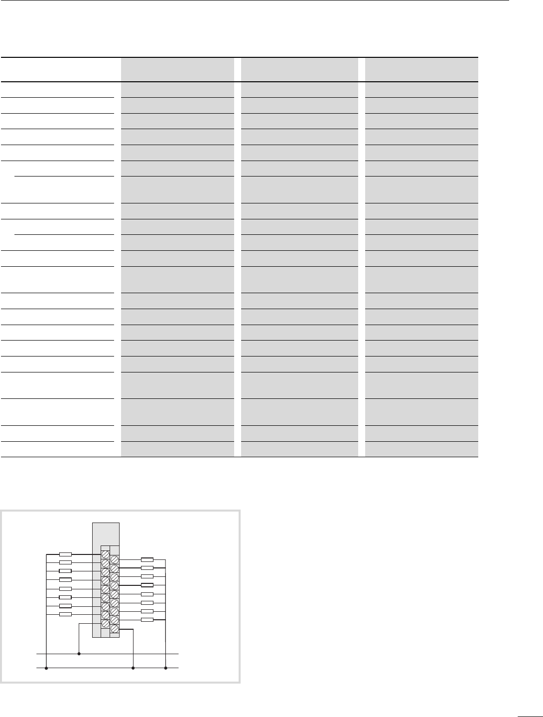
Figure 30: Terminal assignment
+12/24 V H
0 V H
0
1
2
3
4
5
6
7
C
8
9
10
11
12
13
14
15
S
XIOC-16DO(-S)XIOC-8DO
XIOC-16DO(-S)


