11
Note If the meter does not detect the temperature probe, it will
switch automatically to manual temperature compensation
with the temperature adjustable through the up and down
arrow keys. The “°C” symbol will blink on the LCD.
Note All external cables to be connected to the rear panel should
be ended with cable lugs.
• Analog output: Connect an external recorder with a 2-wire
cable to these terminals (#1 on page 7) paying attention
to the correct polarity. A wide variety of output signals,
either in V or in mA, is available to fit most standards.
• Contact 1 and 2: Connect the dosing devices to these
terminals (#4 and #7 on page 7) in order to activate and
deactivate them according to the selected control param-
eters.
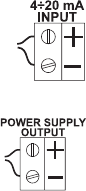
• mA Input: to switch to mA input signal from a
conductivity transmitter (e.g. HI8936, HI98143
or HI98144 series) see setup procedure (code
6). Connect the two signal wires from the trans-
mitter to terminals #11 on page 7, paying at-
tention to the correct polarity.
An unregulated 10 ÷ 30 VDC - 50 mA max.
power supply output (#10 on page 7) is pro-
vided to power the transmitter, if needed.
Once the installation is completed, select the appropriate
working range, the reference temperature (20 or 25°C) and
perform conductivity or TDS calibration as described in this
instruction manual. Set the control parameters according to
the process.


